This thread has been locked.

If you have a related question, please click the "Ask a related question" button in the top right corner. The newly created question will be automatically linked to this question.

BQ25708: - some problems (heat, noise, charge current).

Part Number: BQ25708

Hi all.

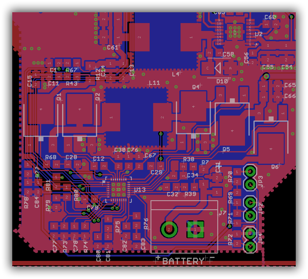
We made several boards with BQ25708 charger. Added schematic + PCB for this part of design.


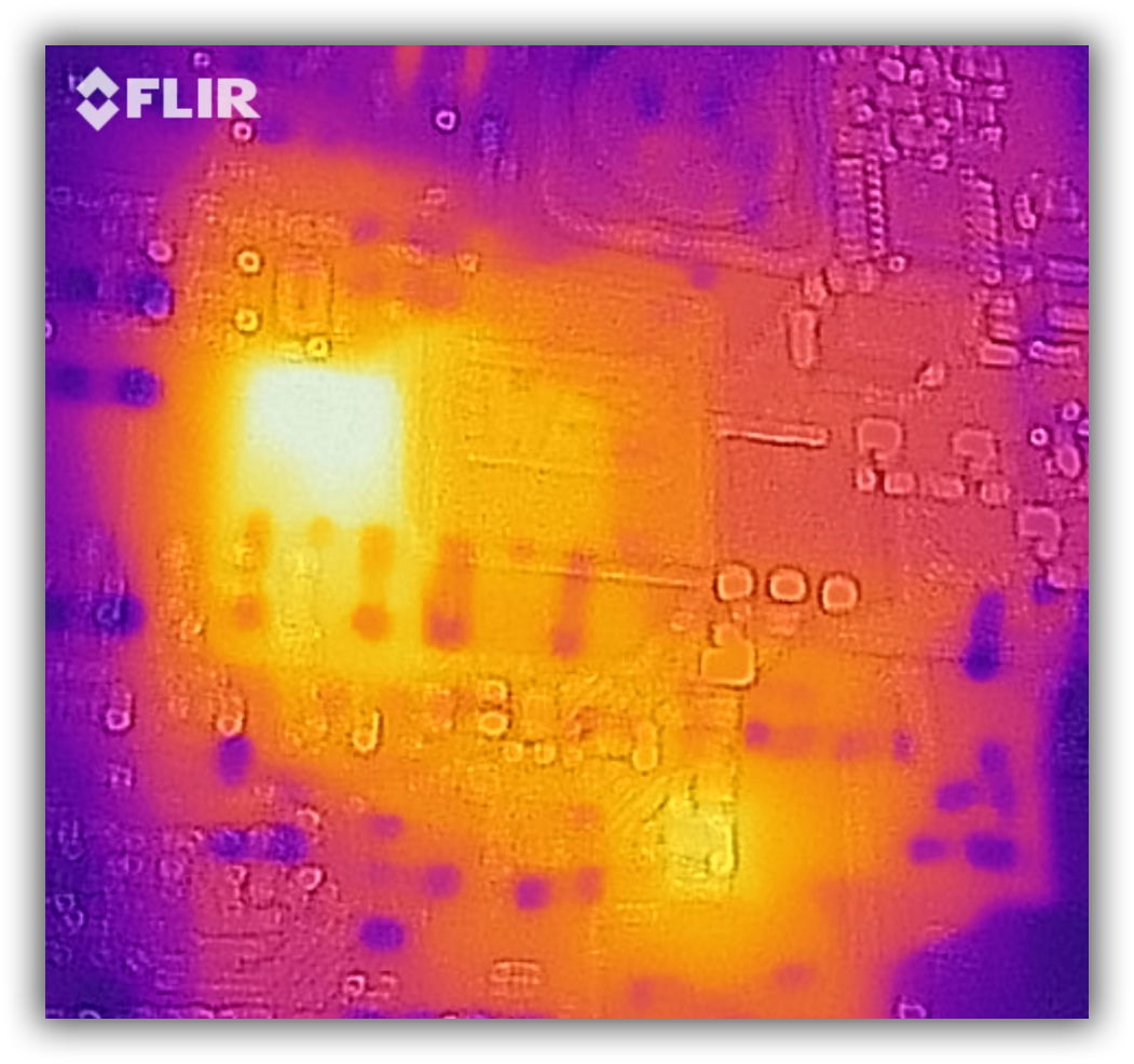
In testing progress we found some troubles. A lot of heat at Q1 and BQ25708.  They very hots. (added thermal photo). 

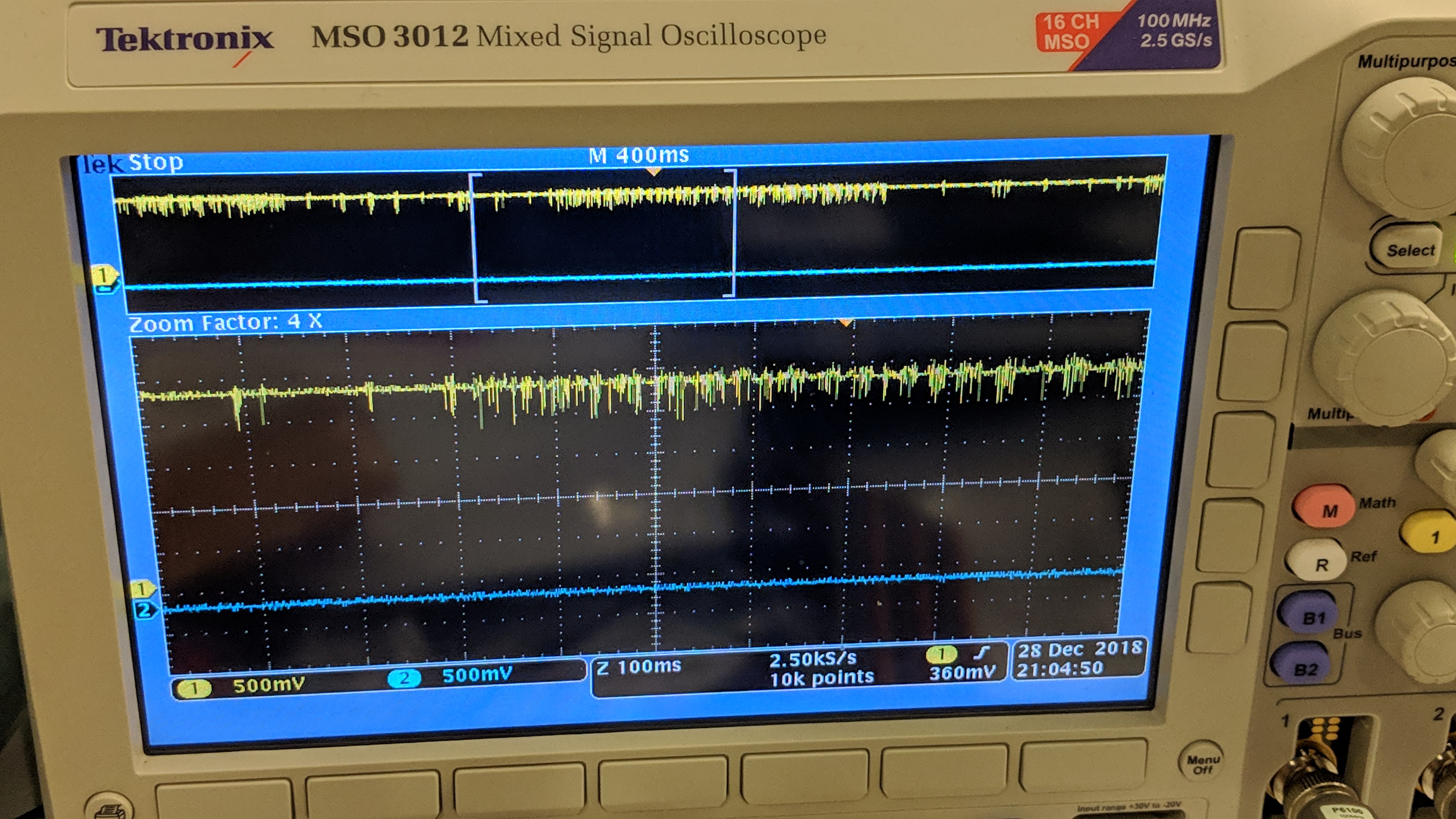
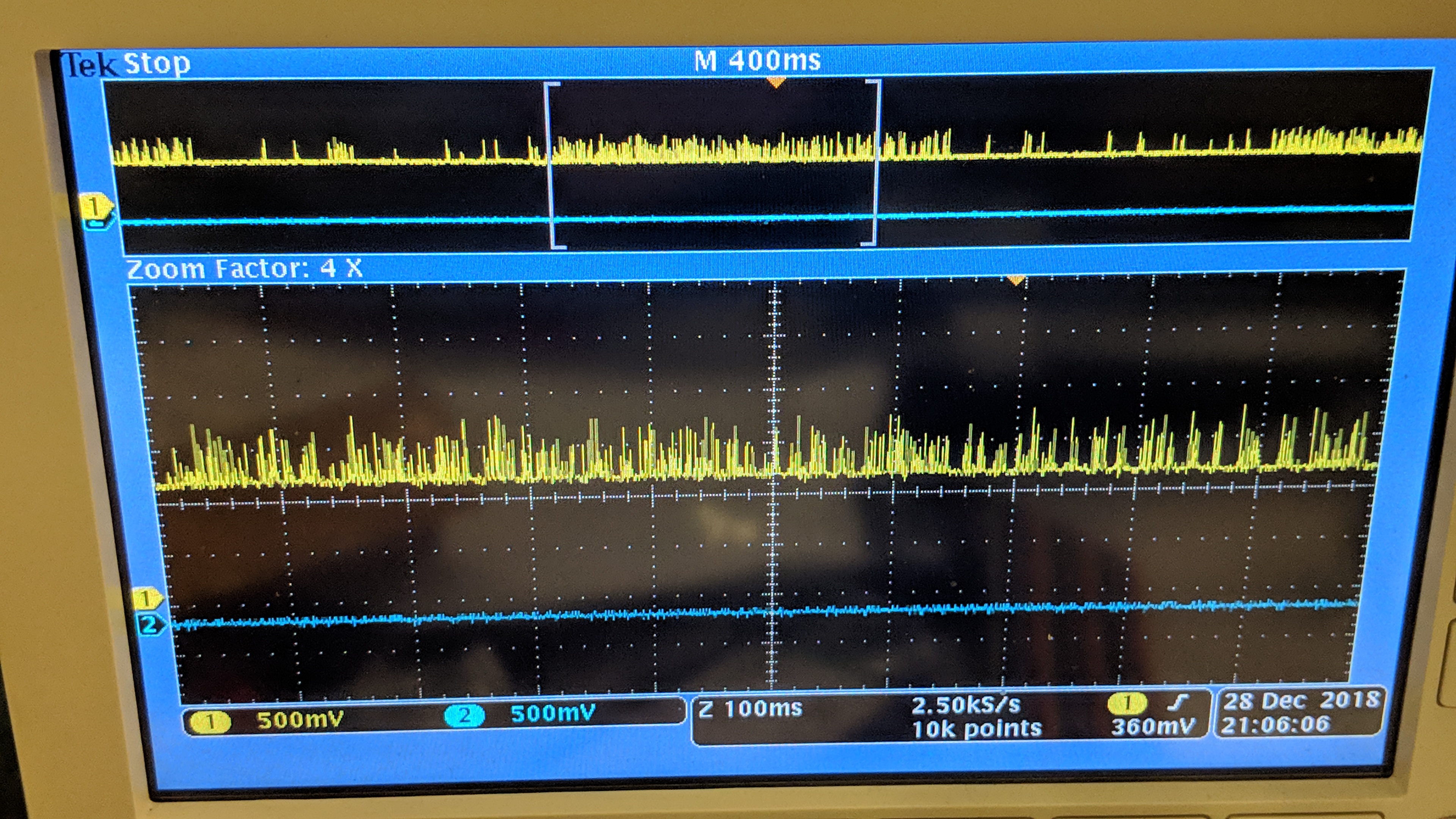
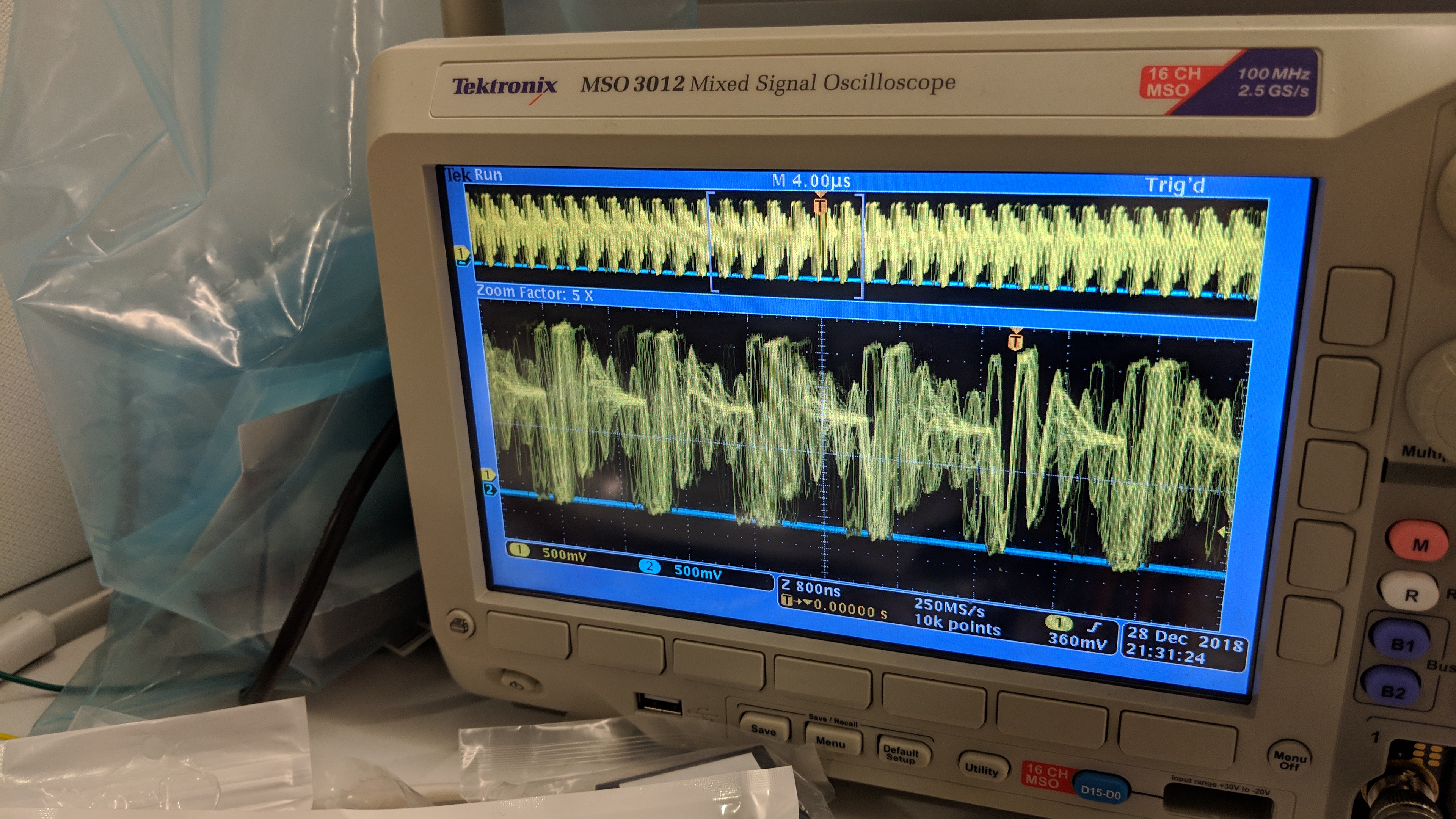
Noise at Vsys, and  strange form for HIDRV1 signal. (Added oscilloscope photos).

Also, I do not see charge current at BQ25708 registers. (I see very small charge current with multimeter, only 5-8 mA). Added log file. 

Thanks advance.

AnatolyBQ25708.pdf     wincorLog3-22v.log

  • Anatoly,

    Unfortunately, our BQ257xx support team is out until January 7th. But they will likely ask some of the questions below:
    1. Are you only operating in buck charge configuration with VBUS=22.5V and VBATREG=12V?
    2. Do you have a current meter in series with the battery? If so, if you remove it, does operation change?
  • Hi Jeff.

    Thanks for reply. 

    1. Yes, our device operate only in this mode. It maybe we will use another battery configuration (LiOn 2-4 cells), but it will be same buck charge mode.

    2. Rechecked current. current meter swing rather erratically from charging of ~200mA to discharging of ~150mA
    battery voltage swings from 10v to 12.6 (charging voltage). Charge current of 384 mA showed up in register.

    Additional info. Battery test with laboratory power supply and load shown internal battery resistance about 1,2 - 1.5 Ohm 

    Still have heat problem. My suggestion about this:

    Mosfets that I used have too big gate capacitance (STD70N10F4 ) - so charger can not give enough peak current and mosfet does not have time to close and open completely

    To check this version I ordered new mosfets (FDD6630A). Waiting for delivery.

    Regards, 

    Anatoly

  • Hey Anatoly,

    I think the MOSFETs are a good start.

    I do have a question about the waveforms you've captured. Are they DC offset or AC coupled in any way? They do not appear to be do but I just want to confirm. Can you take a waveform of the SW1 pin? Please also capture VBUS and VBAT. 

    Can you also removed the battery and just add a load to VSYS. One thing about your last waveform is the oscillation which looks like DCM operation even though you mention it being the HIDRV waveform which just doesn't look correct. The voltage range is also too small for the voltages you are operating under. 

    I also took a look at your log and there appears to be points where these is no log data intermittently within the file. Was there potentially a POR at any point? 

    Regards,

    Joel H