This thread has been locked.

If you have a related question, please click the "Ask a related question" button in the top right corner. The newly created question will be automatically linked to this question.

Buck converter :: parallel

Other Parts Discussed in Thread: BQ24650

Hi,

I have two solar panels which are not mounted on the same location, so they are not exposed to the same environmental conditions - illumination, ...
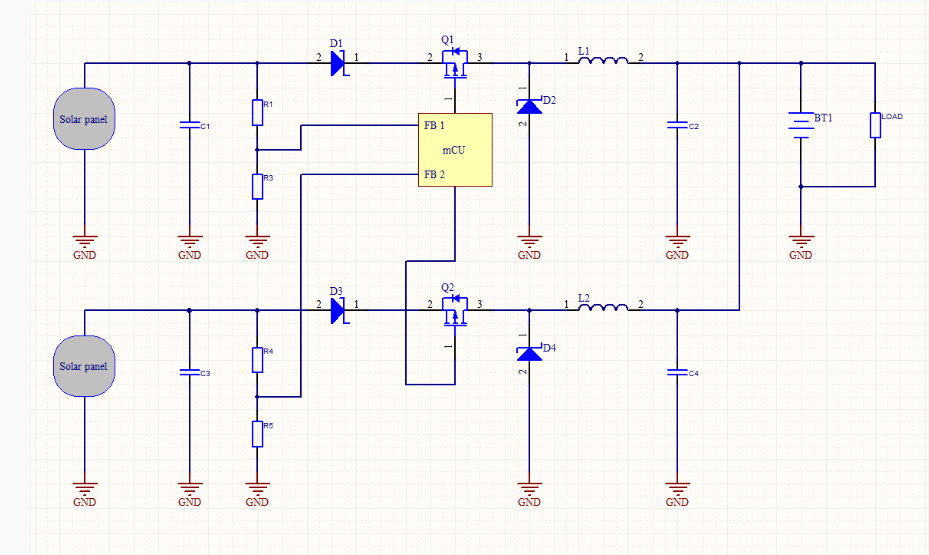
For a higher efficiency of MPPT would like to use a separate buck converter for each of this panels, but because of nature of application I would need to connect outputs of buck converters in a parallel. On the output side of a converters will be a battery, so in one mode, this two converters will charge a battery, in another mode there will be also a load connected in a parallel with a battery, so there is a plan to deliver from solar panels as maximal as possible part of electrical energy, so each solar panel will must work near to maximum power point as possible.

Because I would like to use a separate buck converter for each panel, I must use a separate duty cycle control for each converter (PWM will be generated with MCU). Additionaly, because output voltage is determined by voltage of a battery, I am planning to use a feedback from the input (solar panel), so with duty cycle I will changing an input and not output voltage.

Do you see any problems with parallel conection of buck converters in that example?

Many thanks!
Dejan.

  • Hello Dejan,

    This is a very good question, and the application note below addresses it.

    http://www.ti.com/lit/an/slva829/slva829.pdf

    Preventing BQ24650 Leakage Current When Using Shaded Solar Panels

    The issue with the buck topology is reverse conduction up through the body diode of the top fet.
    When the input voltage is lower than the output voltage, in a buck, current will flow to Vin through the body diode.
    To counteract this, another diode is placed in the path that blocks current from going "INTO" Vin from Vout.
    The additional diodes demonstrated in this application note describes the diode placement.

    As shown below, D1 may be needed if the battery pack does not have its own built in blocking diode.

  • Hello Ed,

    many thanks for fast reply.

    In my example I'm thinking about solution with only D1 diode included in a schematic (according to your scheme). So with D1, there is no possible that current flows from output to input, because there is diode on the input. I'm planning to use a non-synchronous type of buck converter, so there is also no possibility to make a short-circuit, because there is a schottky diode in reverse direction used instead of bottom FET.

    Schematic example:

    What do you think about this solution? Maybe is not so optimal because input capacitor is placed in front of the input diode, but this solution may work I think?

    Many many thanks.

  • Hello Ed,

    here is a schematic example I mentioned in previous post: www.dropbox.com/.../bc.png

    Many thanks.

  • Hello Dejan,

    Your implementation using a diode in the D1 location should work.

    To charge a battery you will need to sense current as well as voltage, in order to control the V I curve.
    TI has an example of using an MSP430 to charge LiIon batteries.

    Li-Ion Battery Charger Solution Using an MSP430™ MCU (Rev. A)

    The software is available via a link shown on page 6 of the PDF.
    http://www.ti.com/lit/zip/slaa287