Other Parts Discussed in Thread: TPS61165
Hi,
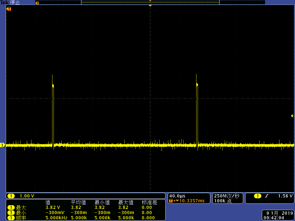
Issue description : My design is use a TPS61169 to drive a LCD backlight circuit (LED number 1*8,Vf(typ)24.8V@30mA ). I find these is very few IC(10/10000) occurs different drive current when we use 1% PWM input at Ctrl Pin (24Khz,3V3 voltage level ) ,the LCD backlight show a lower light brightness,but the same Vfb value appears at 100% PWM input. I switch the IC to another good PCBA,the result is whatever the PCBA we used the failure is always appear at same IC.
measure data&circuit detail :
abnormal IC 1% PWM input Vfb=2mV Vout=20.4V ( Rset=6.8R L=10uH/1.4A Diode MBR0530)
100% PWM input Vfb=203mV
noraml IC 1% PWM input Vfb=11mV Vout=21.1V (Rset=6.8R L=10uH/1.4A Diode MBR0530)
100% PWM input Vfb=209mV
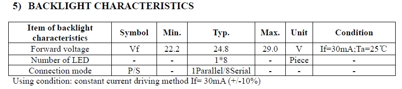
LED backlight parameter :
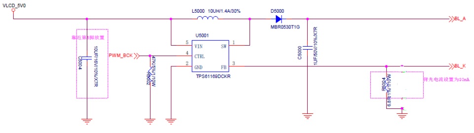
circuit design :
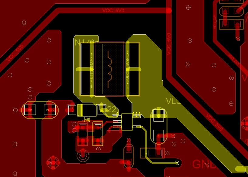
layout picture :
Questions:
1. It there any problem in circuit design and pcb layout ?
2. why the few IC's Vfb value shown like follow the datasheet descripted?but most of IC's Vfb at 1%PWM like NG ( base on the datasheet :Vref=204mV,Iset=204mv/6.8R=30mA,1% PWM ,Iout=0.3mA,Vfb=2.04mA)
3. why the two ICs have a same Vfb value at 100% PWM input but not happen at 1%?
4. In your opinioin, which one is normal IC in this case? The majority of IC or the few?
5. How can I lock the root cause in this case ?
THank you very much !
I am looking forward your feedback.
Best regards,
Jun