This thread has been locked.

If you have a related question, please click the "Ask a related question" button in the top right corner. The newly created question will be automatically linked to this question.

LM3429-Q1: The output current is unstable with LM3429 : Need quick help (Ready for Production)

Part Number: LM3429-Q1
Other Parts Discussed in Thread: LM3429

Dear Sir, 

Greetings!

I need an immediate help in solving the issue with LM3429 for my design. The design details are

Vin : 10-15 VDC

Vout: 24-38VDC

ILED: 0.45A (typ)

Rlim - 0.075 ohm / 0.082ohm 

I'm using 

DMN6040SK3-13 MOSFET and 27uH Inductor. 


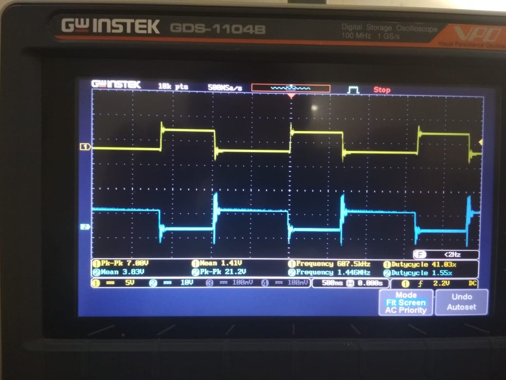
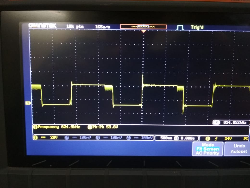
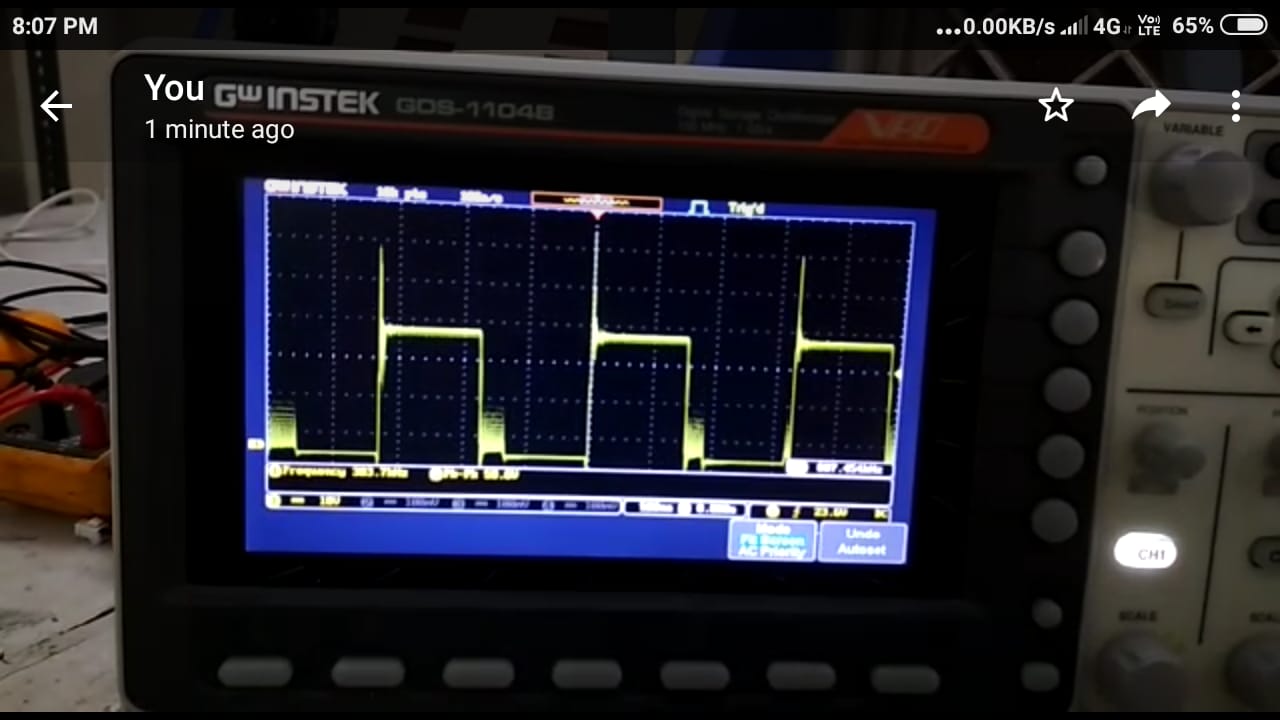
I'm facing an issue with instability in the output current of the driver and  the result might damage the LED load since the current varies from 0.45A to 1.2A . During this issue, all the components seem to be in controlled temperature. I'm sharing the video captured of the MOSFET drain pin during the issue. I need quick response as our Production is planned for next week.   

 I'll share the schematics, gerber and design if you need them in solving the issue. 

Thanks in advance. 

Regards, 

Santosh, 

RND@ayanaenergy.com 

  • Hi Santosh,

    Since we are going to need schematic and more details, it's best if we take this offline.  You can send me your schemtic and gerber file directly via EMAIL to tuan.tran@ti.com

    What you showed above is the drain voltage...Can you have the gate voltage along with this drain voltage in a scope capture?

    Another scope capture:  We will need you to show us the the LED output current when it's un-stable on the oscilloscope along with the input voltage, output voltage, and COMP voltage.  We would like to have part number for the inductor as well.

    Thanks Tuan

  • Dear Tuan,

    Greetings! 

    Please find the drain & gate waveforms here. I have a query on this, the switching frequency in the Webench shows around 600 kHz but the Controller gate switching frequency is found to be >1MHz. Where as the drain pin switching frequency is found similar. How would it differ? 

    The O/p current initially being 440mA and after a few minutes it turns to 1.2A CC. So I've made a change to limit the input current to 1.6A (Rlim - 0.15 ohms). Even the Pk-Pk voltage on drain & gate is also reaching 75V & 21V respectively, which may harm the MOSFET and ICs. I'm trying to change the switching frequency by changing the RCT and Inductors. Still, the issue is not being resolved. I wonder if you can help me out quickly in solving the issue. 

    1. RCT - 39k , Ccomp - 100nF, L - 27uH, Output current CC - 0.45A

    2. RCT - 39k , Ccomp - 100nF, L - 27uH, Output current CC - 0.52A fault condition 

    The peak-to-peak voltage is actually >=70 on drain (The signal captured in 1x mode, please ignore the fault in measurement) 

    3. RCT - 47k , Ccomp - 470nF, L - 330uH, Output current CC - 0.46A

    4. RCT - 47k , Ccomp - 470nF, L - 330uH, Output current CC - 0.56A Fault condition

    The Inductors are Drum core inductors with good quality in local made. We've been using them from last 5 years. The specification of Drum core Inductor is 27uH, 2A, DSR 0.045 ohms (Core size dia x height  : 12x15 mm) .

    Thanks for immediate response. I've shared my gerber and schematics with you in email. Kindly review and help ASAP. 

    Regards,

    Santosh. 

  • Mr. Tuan, I'm waiting for your response.
  • Hello Santos,

    We have received your schematic but it does not have many of the component values on them. We will need you to send us a schematic with values on them and parts that you are not populating. We would also like to have part numbers for L1, Q4, D8, D9, COUT1 and COUT2. Is there a reason that you are paralleling D8 and D9?

    On our previous reply we also ask for the below scope capture but did not get them from you:
    LED output current (current probe) when it's un-stable on the oscilloscope along with the input voltage, output voltage, and COMP voltage. We would like to have part number for the inductor as well.

    We will need the above requests to verify you design first before we look into layout.

    Thanks Tuan
  • Dear Tuan,

    I'll share the updated schematic. I would like to clarify on the LED Output current, initially the output current is stable with 0.45A CC, after a few minutes it is being raised to 1.2A CC with Rlim - 0.075 ohm and is constant at this point.

    As already informed, the Drum core Inductor is local made, hence I can share the specifications, i.e. 27uH, 2A, DSR 0.045 ohms.

    My Scope's Current probes have a problem, so I couldn't take the current waveforms. I'll share the input voltage, output voltage and COMP voltage wave forms very soon in the email.

    Thank you.
  • Hi Santos,

    It's hard to trouble shoot without the scope capture but based on what you given me it's can be stability issue. I've send you a power point presentation thru email with recommended things to try. Please read that and let me know how things go.

    Thanks Tuan
  • Hi Santos,

    I have not heard back from you so I believe you may have solved the issue.
    The thread will close now but will reopen if you reply.

    Thanks Tuan