This thread has been locked.

If you have a related question, please click the "Ask a related question" button in the top right corner. The newly created question will be automatically linked to this question.

TPS25942L: Please help to analyze the cause of FLT trigger

Part Number: TPS25942L
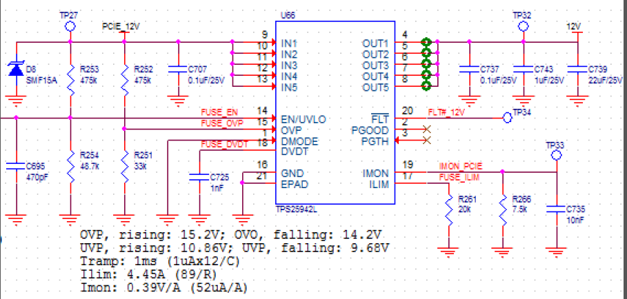
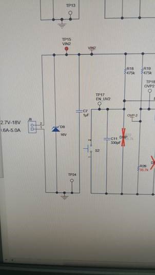
Other Parts Discussed in Thread: TPS25940-Q1

Dears,

Please help to analyze the cause of FLT trigger, thank you!

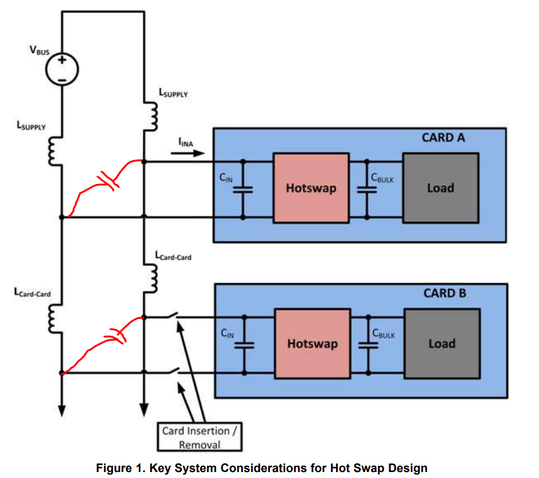
In A SSD server machine frame, there’s a normal working disc A, when we were in the other slot insert disc B (Both disc A and disc B use the SSD of TPS25942L, they are the same products), would likely trigger TPS25942L FLT alarm in the working disc A.

At first we doubt that it may cause the machine box power glitch when we inserted into the disc B, leading to A TPS25942L FLT alarm. After much monitoring, we find that the 12v power supply is normal before the FLT alarm, there is no overvoltage and under voltage phenomenon.

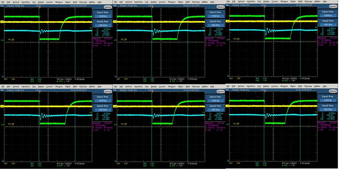
The following bigger graph:

the green line: PLT

blue line: 12V power input

yellow line: NC


So we try the TPS25942L EVM kit.

We do these actions, connected to power development board in the front of SSD (it  is the 12v power supply -> TPS25942L EVM - > SSD card).

It is a pity that the problem is still, the TPS25942L EVM still appear FLT alarm.

This may rule out our board design and layout is quite ok.

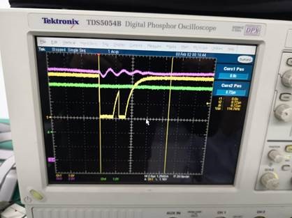
The following smaller figure, red-PLT,  green-12 v power supply, yellow- SSD board FLT.

Please help to analyze the cause of FLT trigger, thank you!


  • Hi Elsa Duan,

    Thanks for reaching out!

    It looks to me that FLT is asserting due to reverse current protection.
    When disc B is inserted Vin rings which triggers reverse protection comparator of the eFuse on disc A. Can you check by adding more capacitance on Vin bus.

    Best Regards,
    Rakesh
  • Dear Rakesh,

    Thank you for your advice.

    The circuit is blow. Can you help me change the Capacitance?

  • Hi Elsa Duan,

    Add 0.1uF to 1uF on the 12V source side (marked in the below image) which helps to absorb the transient introduced from an adjacent card insertion. Please also refer www.ti.com/.../slva703.pdf

    Best Regards,

    Rakesh

  • Hi Rakesh,

    Base on your advice, it's been tested and the problem is the same.

    Test: the Vin capacitance of SSD is increased from 0.1uf to 1uF. The problem is still the same. It can be seen from the oscilloscope.


    In addition, the capacitance of Vin:

    1. The adoption of TI official TPS25942L EVM will also cause problems. Its Cvin capacitor is 1uF, which is shown in the circuit diagram.


    2. We have tried to increase the capacitance of the development plate Cvin to 100uF or even 330uF, but the problem remains.

    Are there other ways to avoid FTE alarms?


    Thank you very much for your help!


    Best Regards

    Elsa Duan

  • Hi Elsa Duan,

    TPS25942L EVM is configured to use the device in power mux configuration, which is different use case from your application.

    The reverse current comparator asserts the FLT output when the Vin drops by 10mV over Vout. This feature is essential for power muxing application which is creating false alarm in your system use.
    One way to overcome this issue is to use device having higher reverse current threshold. TPS25940-Q1 has -66mV threshold and would be more immune to Vin ringing triggered reverse current cut-off.
    Please check with TPS25940-Q1, it is pin to pin compatible to TPS25942L

    Best Regards,
    Rakesh