This thread has been locked.

If you have a related question, please click the "Ask a related question" button in the top right corner. The newly created question will be automatically linked to this question.

TINA/Spice/LM34936: PSpice model for simulating the input line regulation

Part Number: LM34936
Other Parts Discussed in Thread: TINA-TI,

Tool/software: TINA-TI or Spice Models

HI, LM34936 support team

I would like to simulate the input line regulation of LM34936 when LM34936 was used at the back of PD controller because it must support the input voltage range of 5V-20V. There is a "LM34936 PSipce Transient Model" as simulation file in product folder. There are 2 kinds of schematics for simulation as follows. But PSpice library is only one.   


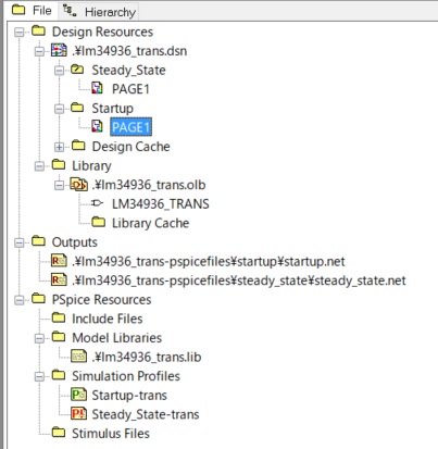
1. Is the same PSipce libray file used to simulate for Start-up and Steady_State?

2-a. If YES, is the difference between Start-up and Steady_State only the input power supply model?

2-b. If NO, which schematic of Start-up and Steady_State should I use to simulate the input line regulation?

Regards,

Tamio

  • Hi Tamio,

    The same model is used in both simulation types.

    I believe the difference between the start-up and steady state is just a difference in the test bench. The Input voltage supply setup is different.

    Thanks,

    Garrett
  • Hi, Garrett

    I got!

    I have already simulated using the customized schematic based on the steady-state schematic. The input power supply, peripheral parts and something was changed.

    Since I look like that the power consumption on BIAS pin when Vin is lower is not considered, I added a load resister on BIAS pin. I took a waveform as my expectation.

    Thanks

    Tamio