This thread has been locked.

If you have a related question, please click the "Ask a related question" button in the top right corner. The newly created question will be automatically linked to this question.

UCC28070: about ' Dmax'

Part Number: UCC28070

Hi,team

First of all,there is no pwm.UCC28070 doesn't work .I check it one by one. I can't find  the reason ,so I recalculated all parameters.And there is a new question,I can't change 'Dmax'.

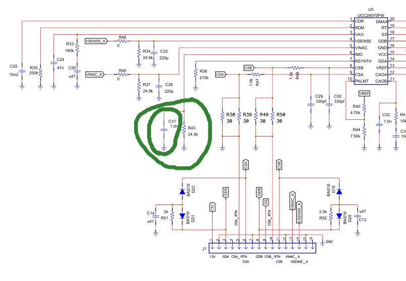
If Vin=0VAC, just through the partial voltage resistance Vsense=2V, Vinac=1V, it can be measured under the condition of maximum duty cycle drive waveform.

I set  fs=100KHz,Dmax=0.9  RDMAX=59KΩ . When    VCC=15V   Vinac=1V  Vsense=2V. I find DMAX=0.66.If I set RDMAX=68KΩ(Dmax=0.95),and I test Dmax = 0.6.Why DMAX is always about 0.6. I changed a new UCC28070. DMAX also equals to 0.6.Before  I recalculated parameters, I can test Dmax=0.9.

Beside these, about Nct,I calculate Nct =592. I find TI set Nct= 0 ~ 200.So I set Nct=200. Whether it is right or wrong.My Lct=84mH.

Here is my mathCAD.Could you please take a little time to check my parameter calculation right or wrong ? 

Thank you!

NEW3500WUCC28070 Design Tool .doc

  • Hello jiannan li,
    Can you please attach a schematic that shows your circuit and the input test conditions used?
    If you want to check the actual DMAX value then you should run the pfc open loop with VSENSE and VINAC greater than 1V and less than 3V.
    You dont need to connect a high voltage input for this test.

    Regards
    John
  • Hello John,

    Thank you for your reply. Here is my schematic.In this  schematic I don't use flyback power.

    I use external auxiliary power module to supply control circuit power and not connect a high voltage input.

    I run the pfc open loop with VCC=15V, Vsense=1.8V, Vinac=1.1V.

    Question 1: No matter how I change the RDMAX, DMAX always equals to about 0.6. Why?

    Question 2: I saw a case PMP4259  ( http://www.ti.com/tool/PMP4259)  (http://www.ti.com/lit/df/slur294/slur294.pdf) about PFC part.

    Why is IMO pin external resistance in parallel with a capacitor. In TI UCC28070 datasheet I don't find a capacitor connect to IMO pin.

    Question 3:I can't find Roa in (http://www.ti.com/lit/df/slur294/slur294.pdf). Doesn't it use Roa? If so , why?

    Best Regards

    jiannan li

    4643.PFC.pdf

  • Hello jiannan li,
    Your schematic shows an expected pwm frequency of 100kHz and a max duty cycle of 0.89.
    Do you have a scope plot of the GDA or GDB output ?
    If you are not getting a duty cycle close to 90% then either:
    (1) The ic is damaged and should be replaced or
    (2) Your test board is not built according to your schematic.

    I recommend that you disconnect the gate drive resistors R10, R16. Then look at the GDA waveform with a calibrated scope probe, replace the UCC28070 with a good part and check your board and all the component values.

    Regards
    John
  • Hi jiannan li,
    I am going to mark this post as closed since there has been no response for a few weeks.
    Please open a new post if you have further questions.
    Regards
    John