Hi teams
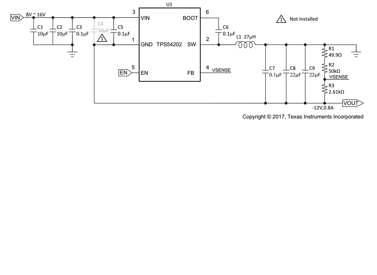
My customer is using TPS54202 as inverting buck-boost topology to convert 12V to -12V as the audio power supply.
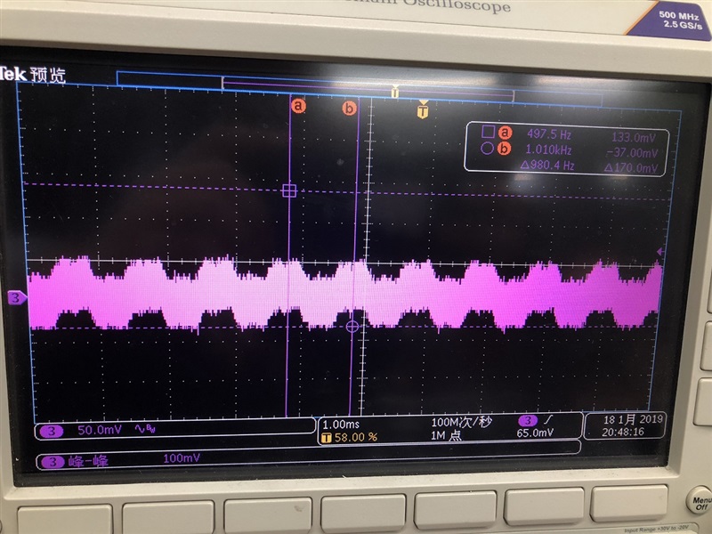
A low-frequency ripple founded in output 's waveform (1Khz frequency) and the audio output have audible noise.
Customer schematic is followed by our application note (SLAV993) and is shown below:(customer change R1 to 1.5Kohm/R2 to 56 Kohm/R3 to 3Kohm) C4 not installed.
The abnormal output waveform contains 1Khz ripple is shown as picture 2.
I have also tested the SW waveform and found the duty cycle is not stable and it seems the loop is not stable.
The SW waveform is shown as picture 3.
I wondering to know:
- Why SW waveform is not stable?
- Why the loop seems unstable? As this device compensated internally, with the same LC filter value the loop characters should be the same.
- Why we need C4/C5 in this topology? What overcome it will be if we did not install C4?


