This thread has been locked.

If you have a related question, please click the "Ask a related question" button in the top right corner. The newly created question will be automatically linked to this question.

TPS1HA08-Q1: TPS1HA08-Q1 Circuit Review

Part Number: TPS1HA08-Q1

Dear TI Team,

I am designing the TPS1HA08-Q1.
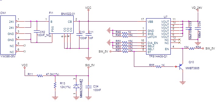
We want to control TPS1HA08-Q1 with hardware only, without using Micom.
We simply use the On / Off function, and configure the circuit to reset by turning the EN low by the switch diagnostic feedback using the ST.
Can you review the circuit diagram for any problems?

Thanks.

  • Hello,
    Are you worried about reverse battery condition? If that is an applicable fault you should have the resistor diode network for the GND pin on the TPS1HA08-Q1 highlighted in Section 9.3.1.5 of the datasheet.

    What load are you driving? On the schematic it only shows a ~10uF load. What else is it connected to? Resistive load? more capacitive load? inductive load?

    Also which version of the device are you using? This will affect where the current limit threshold is.

    During a fault the ST pin will go low which in your schematic will cause enable to go low and ST will wait "tretry" from the datasheet amount of time then ST will go away and it will be enabled again. However this to me seems like the exact functionality of the device if you use A/B/E versions. Those devices (with latch=0) will continually retry after a fault. In my opinion I don't see really what the PMOS transistor would be helping. It seems unnecessary to pull down EN during a fault since the switch already turns off.
  • Dear Cameron,

    Thank you for your reply.

    We use it as follows.

    1. The load current is used in the LCD panel and the processor, and Max 24V 7A is used.

    2. I do not use the battery.
    Use an adapter.
    Do I still need to add a diode to GND?

    3. It is designed to apply EN to the ST pin and EN pin by pulling up 5V, and when the fault occurs at the ST pin due to PNP TR,
    EN is low and the output is cut off.
    If an error occurs in ST, does the output occur when EN is High?

    Thanks.
  • Hello,

    1.I would recommend that you use the TPS1HA08A-Q1 device that has a current limit at 20A at room temperature. However are you charging a large capacitor? Will you need to handle inrush current correctly?

    2.If there is any risk of connecting the adapter incorrectly you will need to add the resistor and diode on the IC ground pin

    3. Please see figure 44 of the datasheet. When a fault occurs, the ST pin will pull low and the output is turned off (enable is still high). The part waits for "tretry" amount of time and the tries to turn back on. All of this occurs with the enable high, therefore enable does not need to go low when a fault occurs because the device itself will shut off

  • Hello.

    Thank you for your reply.
  • Dear Phillips,

    The TPS1HA08A-Q1 was designed and tested.

    Our usage specifications are as follows.

    1. Vin: 24V

    2. Lout: Max 6A (LED Panel Back Light) , Continuous load current 4A

    3. Do not use MCU

    4. Fault function is used. (Output cutoff)

    5. Symptom :

        1) Fault occurs at initial start

        2) The ST pin operates normally up to 1A when the pull-up resistor is removed, but a fault occurs at the 4A load.

        3) Removing the diode connected to GND causes the same symptom as item 2

    6. Requests :

        1) schematic Review

        2) Do you have a TPS1TA08-Q1 product?

             In the data sheet, 12V is TPS1HA08-Q1 and 24V is TPS1TA08-Q1.

        3) Please ask us if it is appropriate for the structure we are using.

    7. Below is the schematic we designed & waveform.

    * Waveform of ST pin designed according to circuit diagram

    When the diode of GND is removed and 4A Load is given, the waveform (ST Pin)

    Please review.

    Thanks.

  • Closing this thread as it is being asked in a different thread.