Hi team,
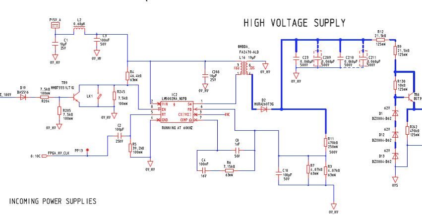
I'm using LM5002 switching IC to create a high voltage DC supply of +240V in association with 1:8 transformer. Input supply voltage to switching IC is +15V and internal switching frequency is ~ 325KHz with RT set to 39K2.
A segment of the schematic is outlined below and I'm looking to obtain:
-
Required values for the compensation network formed by C8, C4 and R6 when RT is 39K2 (as per schematic).
-
Compensation values for switching frequency of 512KHz. Please also include RT value.
-
Compensation values for switching frequency of 1024KHz. Please also include RT value.
The DS for LM5002 provides the formulae’s for calculation the poles/zeros, but no indication on how to obtain the phase margin.

