This thread has been locked.

If you have a related question, please click the "Ask a related question" button in the top right corner. The newly created question will be automatically linked to this question.

TPS62260: The part is getting damaged.(Output gets short with GND)

Part Number: TPS62260

Hi,

We are using TPS62260DDCR part as DC DC converter in out products. It was found that the part's output gets shorted with GND.

Following are the design details with the existing:

1.) IC TPS62260DDC

2.) Inductor used is NLHF303012T-2R2. Find the link for datasheet download www.core.com.tw/search.asp

3.) Total Output Capacitance is 33uF.

4.) Total Input capacitance is 100uF.

5.) Divider used are R1=14K8(1%) and R2=3.3K(1%). For generating ~3.3V. External Feed forward Capacitor used(C1) as 22pF.

Here the layout is not a concern as i have the EVB board as well with me. The same IC with EVB board gets damaged. As the output voltage gets short with the ground.

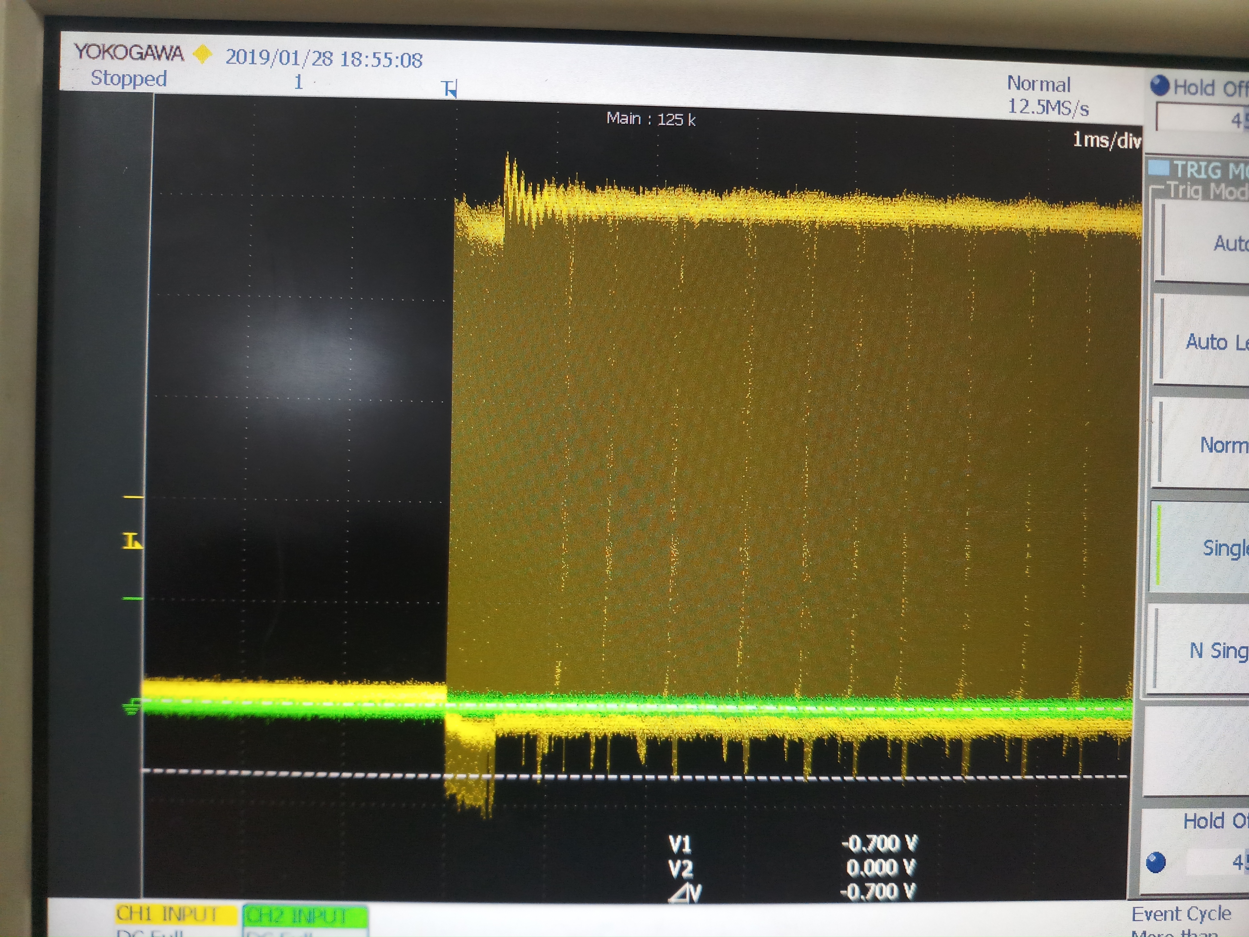
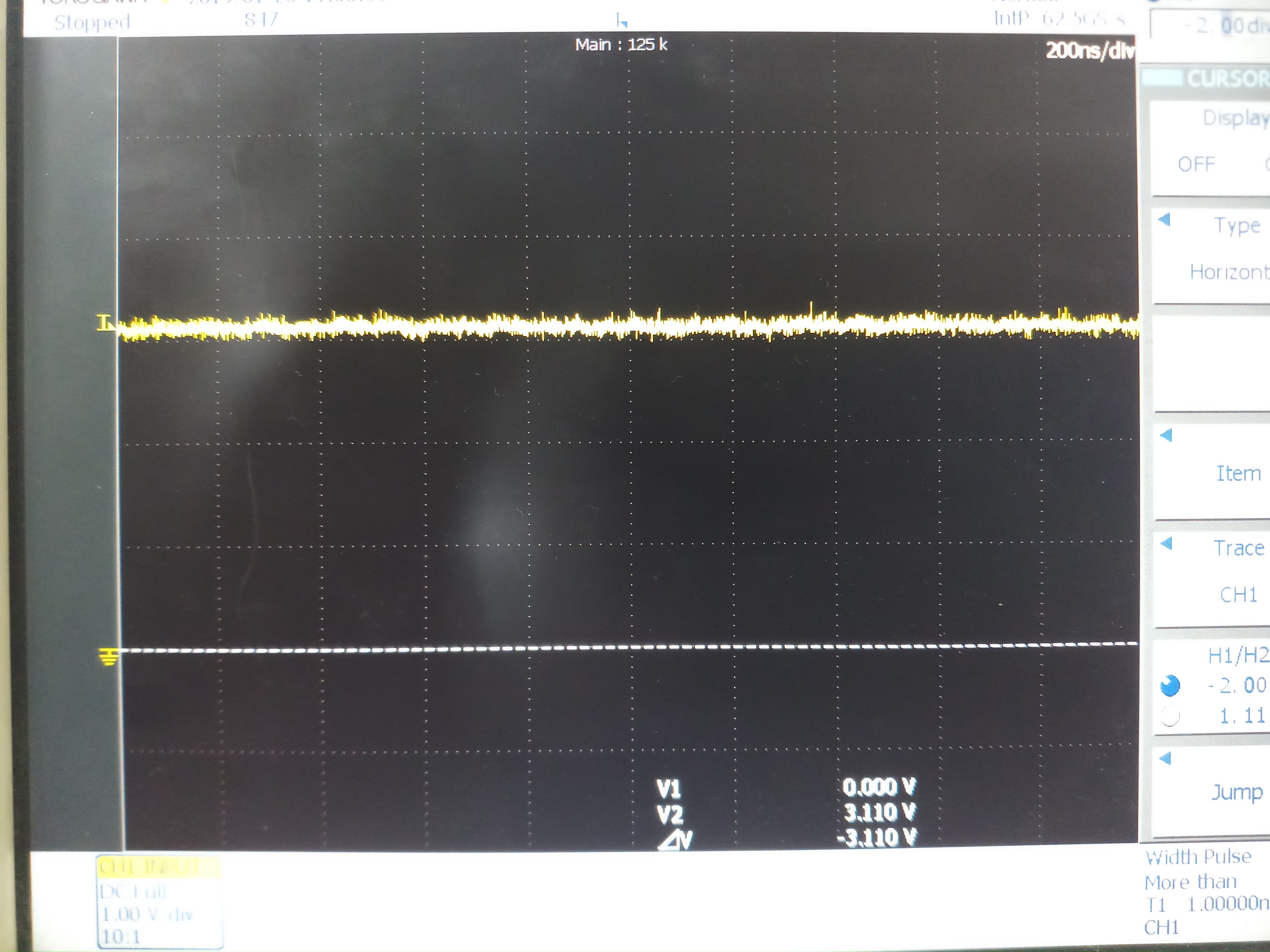
Here we are facing the issue from the field for the IC getting shorted to Ground. On analysis it was found that during power on the IC switching waveform of goes below 0V. Can this be the reason for the IC failure. As this is observed in the 5V to 3.3V generation.

Also it was found that the if the inductor is shorted the IC gets damaged. This was the case when Vin=5V and Vout=3.3V(Iout = 300mA). This was repeated 5 times. Every time the IC was shorted.

While in case Vin =5V and Vout=1.2V(Iout=300mA), if inductor is shorted, The IC gets intoshutdown mode and recovers back properly. This was repeated 10 times no damage were observed.

Can you suggest the reason for above and the observation. Is there any issue in the part?

Also we need to know the internal N-Channel MOSFET ratings? 

  • Hello,

    can you give me more info:

    1) How did you modify the BOM (also on the EVM)?

    2) Did you also modify the EVM before to notice this problem?

    3) Can you send me a schematic?

    4) What means that the IC is shorted? At which pin did you measure the short?

    5) Can you send me scope plots? Try to include Vout, Vsw, Il (inductor current)

    It is normal that the switching node became negative because it is due to the conduction of the body diode (in synchronous configuration). If you intentionally test your board or our EVM shorting the inductor, this is a not recommended action. The rating is specified in section 7.1 of the datasheet (page 4).

  • Hi,

    1.)How did you modify the BOM (also on the EVM)?

    -->  We haven't modify any design in the EVM board.

    2.) Did you also modify the EVM before to notice this problem?

    --> The design detail stated is on our board.  

    3.)  Can you send me a schematic?

    --> 

    4.) What means that the IC is shorted? At which pin did you measure the short?

    --> The Vout shows 1ohm w.r.t Ground. It was measured after the output capacitors.

    5.) Can you send me scope plots? Try to include Vout, Vsw, Il (inductor current)

    --> Scope plots for SW node during startup with EN pin connected to VCC (image1), Switching node waveform with Capacitor(1UF) across R126(asperabove design) on EN Pin in order to add soft start on the input voltage(Image2), Output Voltage in DC coupling mode (Image3), Output Voltage in AC Coupling mode(Image4). While measuring the care is taken that the ground tip is connected directly with the CRO probe. While the measuring tip is connected directly to the SW node/output capacitor as per the measurement taken.

    ALL ABOVE DETAILS PROVIDED IS OF OUR BOARD.

    6.) It is normal that the switching node became negative because it is due to the conduction of the body diode (in synchronous configuration).

    If you intentionally test your board or our EVM shorting the inductor, this is a not recommended action.

    The rating is specified in section 7.1 of the datasheet (page 4).

    --> Regarding the negative spike it is clear and we have gone through the document SLVA494A. 

    --> Fine it not recommended action, This was intentionally done to create the failure, but on further observation and analysis it was found that the part gets fail. Other than that even if you probe the CRO pin on the SW node it also damages the IC. While, if the Input voltage is reduced to the 3.3V and the output inductor is reduce to zero. The IC goes under shutdown mode and gain recovers back. The damage occurs only in with 5V input and 3.3V output.

    --> I forgot to mention that we specifically require the voltage rating of the internal MOSFETs?

  • Hi,

    In context to the failure observed in our board. The lower side MOSFET is shorted . While the input and the switching pin is open(High side MOSFET is not damaged).

  • Hi,

    Any update for the above query?
  • Hello,
    I see different things to change:
    1) input capacitance quite big
    2) IC on the schematic is different from the part number reported in the thread
    3) Mode pin is missing
    4)your feedback divider gives you 3.14V (output) and not 3.3V
    5) the use of snubbers such as R123 and C129 is not recommended and not reported in our documentation
    It is highly probable that the last point is the cause of your problem. Please, follow our documentation and try to change what I noticed. I am going to close this post, but feel free to open a new thread if you still have a problem after the fixing actions mentioned above.