Dear Colleagues,
we use for a longer time the device UCC3895DW in some power supplies in
phase shift and current mode topology.
Sometimes we have problems with the output pulses and therefore destroyed full power bridge transistors.
We recognize unsymmetrical pulses at the OUTC/OUTD side and not a
duty-cycle at 50% constant. Often actually longer pulses with double time!
Particularly in case of using the current sense Pin12 at 2V limiting and 2.5V disabling.
I constructed a test-setup in order to investigate this behavior.
Conditions:
Pin15 VDD 12V bypassed with 10µF and 2x 220nF
Pin4 VRef 5V bypassed with 1µF and 220nF
Pin9 DELAB R=4k7
Pin10 DELCD R=4k7
Pin 8 RT R=110k (further test with 70k and 700pF at Ct)
Pin7 CT C= 370pF
Pin1/2 EAN/EAOUT connected
Pin20 EAP control signal PWM 0-3V
Pin11 ADS to ground
Pin5/16 GND/PGND connected the ground plane directly under the IC.
Frequency about 100kHz (200kHz Pin7 CT).
Operation in voltage mode.
Operation with output power DC link about 100V.
Operation without output power DC link 0V.
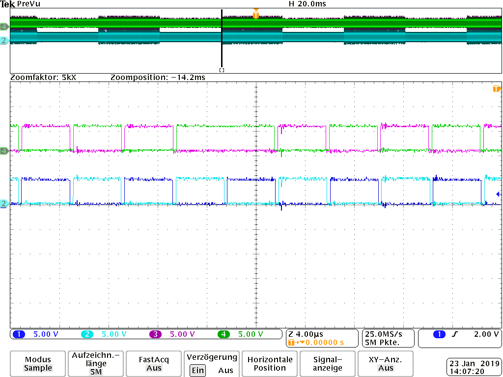
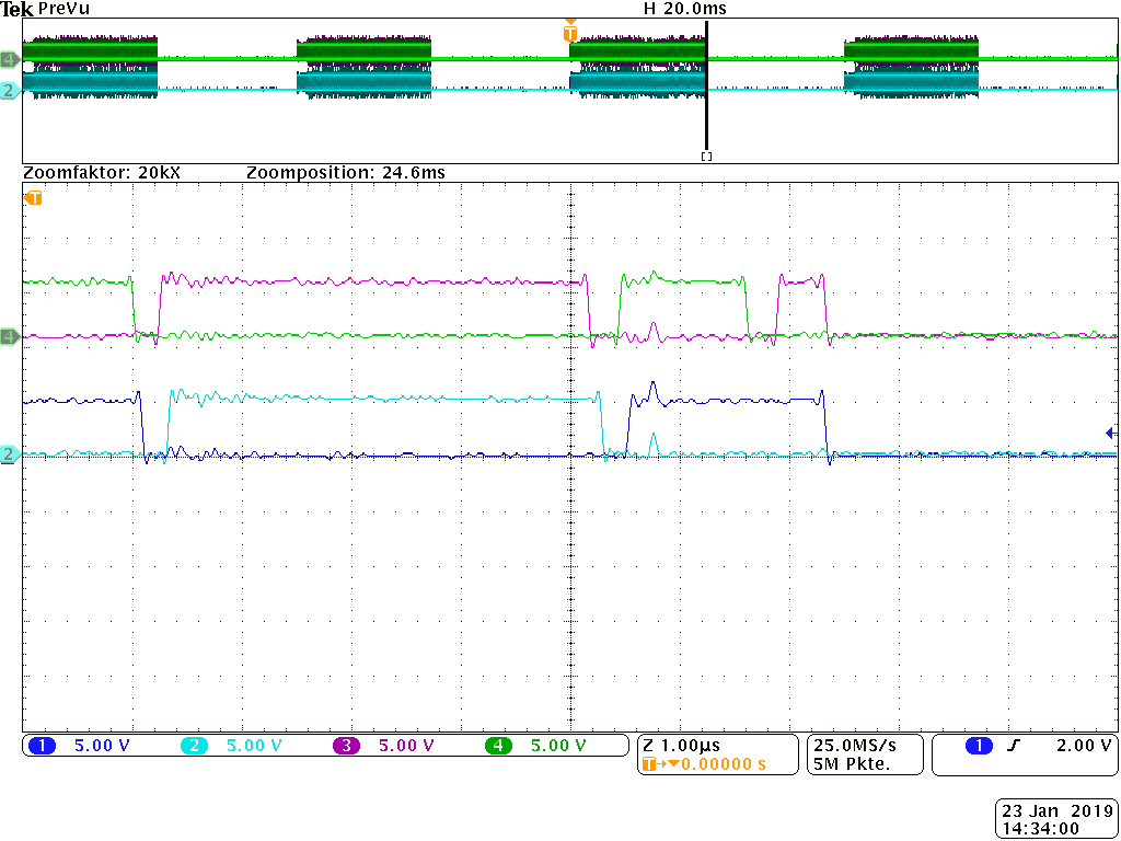
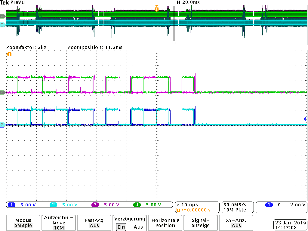
I set a signal rectangular to the input of CS Pin12 with a frequency generator.
First step from 0V to 2.2V (limiting) [00016;00017]
or 0V to 2.6V (disabling) [00023;00024].
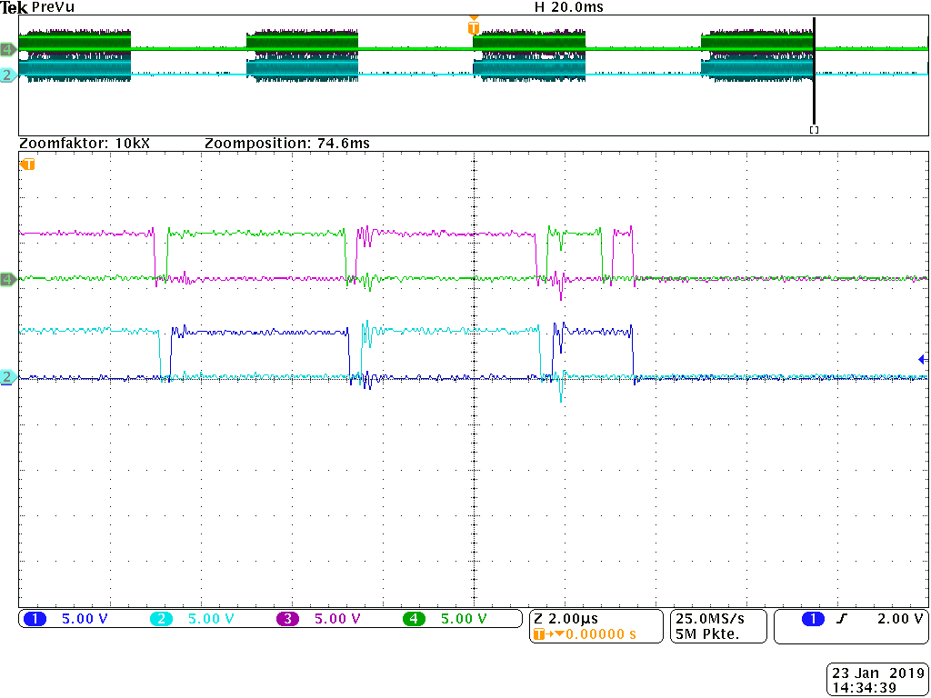
Another example with triangle signal 0V to 2,6V (disabling) [00029;00035].
In any kind we can produce such unsymmetrical and longer pulses.
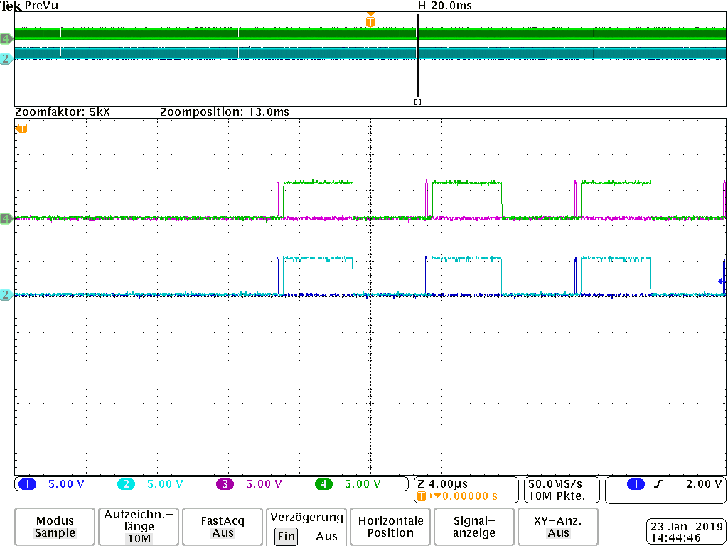
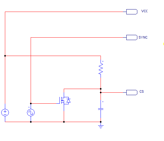
Next experiment was to switch the shut down directly with a mosfet transistor and
frequency generator. In this case there wasn´t visible an unsymmetrical pulse.
[00056;00057]
See pictures at the attachment.[….]
Our question, how can we prevent such behavior and can ensure that we have no
longer pulses and a duty-cycle of 50%?
Thank you very much for your effort.
Best regards
Matthäus Gottenöf
Development