


My customer would like to know what the maximum current draw he can expect to see into the REGIN pin.
I read through the e2e post: e2e.ti.com/.../638989 REGIN
And I agree that the datasheet mentions a 10mA max for Flash programming, and I see that there is an indication of up to 16mA on the 2.5V regulator rail (Section 6 of the EC table).
The reason for the question: The customer design has a 50mA fuse in-line with the REGIN pin for Intrinsic Safety reasons and from time to time is seeing it blown.
Why?
There are no LEDs in the design. The battery is a 1s1p single cell Li+ battery. 4.2V max.
I reviewed their schematic and all looks well.
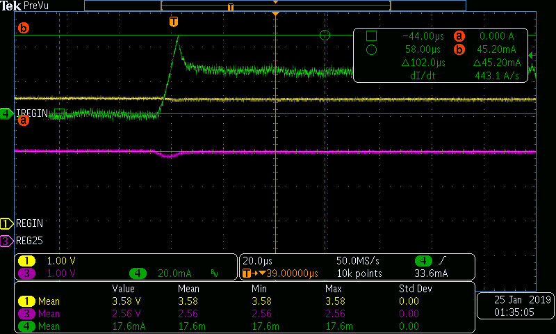
An observation by the customer: They have captured a 25mA current spike in the REGIN pin - that lasts for 120mS. (looks like a square wave). Another spike (looks like an actual spike, and not a square wave) of 45mA.
Scope plot attached here.
Thoughts on this?
Here is the customer comments:
"The issue is that we are seeing that a 50mA fuse is blown on some of the packs. This fuse connects the Vbat+ to the Regin pin. I am also attaching the schematic. The fuse is replaced with a small wire loop to measure the series current.
3 scope plots are attached as follows.
- Current spike 46mA.bmp: Shows the current spike on CH4 of around 46mA (I have seen this exceed 50mA sometimes). CH1 is the REGIN which currently shows 3.6V. CH3 is the REG25 which shows 2.56V with a 0.22V dip when this spike happens.
- Spike time 20sec.bmp: shows that this spike is repeated after every 20secs.
- Spike width 120ms.bmp: shows that the width of this pulse is around 120ms.
"

