This thread has been locked.

If you have a related question, please click the "Ask a related question" button in the top right corner. The newly created question will be automatically linked to this question.

LMZM33602: Excessive heat from dc-dc buck converter nowhere near maximum load

Part Number: LMZM33602
Other Parts Discussed in Thread: , LMZM33603

Hello,

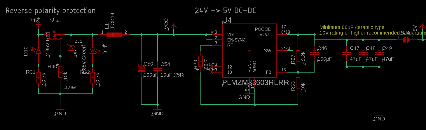
I have integrated the mentioned DC-DC power supply into a board. However upon booting it up I've noticed it gets fairly hot to the touch while the load is barely 500mA @ 5V. Is this normal for this particular chip or is there something wrong in the design?

I've attached the schematic used. The chip that is being used is the 2A version, not the 3A like the schematic suggests.

Frank

  • Hi Frank,

    The schematic that you've provided follows the typical application schematic found in Section 8.2 of the datasheet. What is the maximum ambient temperature you have your system in? How large is your copper area?For a 24Vin -> 5Vout @ 2A application the expected power dissipation is roughly 1.3W. You can use this information and your expected maximum ambient temperature and plug it into the thermal resistance equation found in Section 10.3 to see whether you are within the recommended copper area. 

    Regards,

    Jimmy 

  • Hey Jimmy,

    The ambient temperature is room temperature(20-25). If I touch the underside of the PCB which is shown in the picture, it's almost painful to the touch. This small GND plane is connected to the internal ground plane that covers the whole board(4 layer PCB) with the via's. The output of this chip is NOT connected to the power plane of the PCB(different voltage). This heat seems excessive while the whole system is only using 2W(what the bench PSU shows, so input power). On the left is the chip that is using most of that power, which is also connected to the ground plane in the same manner.


    If we assume that the DC-DC converter is 85% efficient(typical characteristics for 24V->5V shows roughly 87% efficiency at this load) this would mean it should only radiate about 0.3W(datasheet confirms in chapter 6.9, figure 10), which should feel fairly cool to the touch. But when I touch the board I can clearly feel that most of the heat is coming from the converter and it's almost painful...

    What could cause this?

    Emre

  • Hi Emre,

    Can you provide a scopeshot of VIN, VOUT, and SW? This part is a 2A rated part so it is very suspect that it would be painfully hot at only 500mA loading. How often has this failure occur on your board? If you swapped this out with a new device will the same issue occur? If you have thermal vias on that small GND pour to a larger internal GND layer than that should dissipate most heat through the board and the device shouldn't be running hot.

    Is your power supply from a battery that might have voltage spikes or is it stable? I want to make sure that there has not been any EOS on VIN that could damage the part and run this device hot.

    Regards,
    Jimmy
  • Unfortunately this is a single prototype board with a single ic available which is why I suspected a flaw in the schematic at first.

    I will get the scope readouts in the course of next week.

    I've also noticed a high-pitch whining coming off the board at the dc-dc converter, which seems to be the electrolytic capacitor(100uF)

  • Hi Frank,

    Yes when you get the chance to measure some scope readouts please send them over for me to take a look at.

    Some things that came to mind for you to check are the followings:

    • Can you confirm that the device is properly soldered down? I'd like to make sure that Pad 18 has enough solder and is connected to a power ground plane using multiple vias for good thermal performance. 
    • Could the electrolytic capacitor be damaged somehow? Perhaps replace the electrolytic capacitor with a new one and retest. Having damaged capacitors will impact the overall effective output capacitance and stability of the device. 

    Regards,

    Jimmy 

  • Top one is the output on a only a 330ohm resistor for reference. You can see that it shoots upwards to 5.9V, which is nowhere near the specs given in the datasheet. Other photos are with other IC's behind it, including another DC-DC converter.

    Second one is the output of the SW pins.

    Third one is the input.

    Last one is the output when everything is hooked up normally. It's fed by a bench power supply with it's own noise.

    There are audible noises coming from the chip as well. The electrolytic capacitor is fresh out of the box.
  • Hi Frank,

    How many of your boards exhibit this failure event? Can you swap this device with a new LMZM33602 and see if the problem goes away? Again your schematic looks okay and from your description of the PCB layout I believe your circuit should not experience the thermal stress that would result in the part running hot at 500mA. Your application of 24Vin to 5Vout is a common operating condition that can be tested on the LMZM33602EVM.

    What are you powering on the output of the LMZM33602 device? What did you meant by "The output of this chip is NOT connected to the power plane of the PCB(different voltage)". What is the output of the LMZM33602 connected to? The datasheet recommends using large copper area for power planes (VIN,VOUT, and PGND) to minimize conduction loss and thermal stress. Can you show me the VOUT copper plane from your PCB snippets? 

    Regards,
    Jimmy


  • This is the full circuit that exhinibits this behavior. The output is disconnected from the rest of the circuitry. The L1 inductor(noise filter) has been removed and simply bridged, which improved the performance but didn't fix it.

    I'm currently not able to test a new one of this chip because of practical reasons. There is currently only 1 board and simply removing the chip is not possible because of the significant thermal plane.

    VIN is not connected to a thermal plane and VOUT only has a small plane on the bottom roughly the same size as you can see in this layer connected with 9 via's. It gets extremely hot to the touch.

    If thermal planes on VIN and VOUT are required that's a problem for this board.

  • Hi Frank,

    It is primarily important to have multiple thermal vias from PGND pin to a power ground plane for good thermal performance. Having large copper areas on VIN and VOUT will definitely help with thermal stress. What is also important is the PCB copper area of the circuit. Let's assume worse case scenario of 24V to 5V conversion at 2A current loading. At the ambient temperature that you have (20C - 25C) the recommended ThetaJA = (125 - 25) / 1.3W = 77C/W. Looking at Figure 42, you may be able to achieve that at 10cm^2 which turns out to be 30mm x 30mm copper area.

    Since you said that the small GND plane is connected to the internal ground plane that covers the whole board this sounds sufficient for thermal dissipation. You state that you noticed a high-pitch whining coming off the board at the dc-dc converter. Perhaps the internal inductor has EOS damage which would affect the inductance of the inductor result in a lowered maximum loading capabilities of this device. If the inductance is somehow compromised then it could be running hotter than expected. How well regulated is the input voltage into the LMZM33602? Does it ever spike above absolute maximum? 

    Regards,

    Jimmy 

  • Hey Jimmy,

    The chip was only connected to 2 different DC-DC bench power supplies, which are relatively noisy but can't even reach above 30V. Different brands/types and they exhibit the same problem on the LMZM converter. A probe also shows that apart from the noise are pretty stable. I will try out different frequencies to rule out any oscillation issues that might be happening from the capacitance value in combination with the frequency and internal inductor, since removing the filter inductor(L1 as mentioned) reduced overall power consumption and heat of the system(it's still high, but lower).

    Frank

  • Hi Frank,

    I haven't heard back from you, I'm assuming you were able to resolve your issue. If not then please post a reply below.

    Regards,
    Jimmy
  • Hey Jimmy,

    I tested the power supply again by removing the RT resistor set at 450kHz, which defaults the chip to 400kHz. This significantly improved the performance from 150mA drawn @24V to around 90mA @24V on the same circuit. I also tried a 800kHz resistor which gave the exact same behavior as using a 450kHz resistor. What might be causing this?

    Kind regards,

    Frank

  • Hi Frank,

    You might be interested in ordering a LMZM33603EVM to do a side by side testing between your board and the EVM.  This way you can have a direct comparison and understanding of what the expected operation of the device should be at any given conditions. The results you've detailed is not something that I've seen happen when using the EVM. I understand that you can't swap the part for a new one, but doing so will give great insight on if the part was somehow damaged or if it is an applications problem where the system consistently fails. Again 24V to 5V at 450Hz is a common application that is even showcased on the LMZM33603 datasheet. This condition has been tested and verified to work throughout the entire output current range of the part. 

    Regards,

    Jimmy 

  • I will consider this as solved, however if I find out why this happened to this particular board I'll drop a message. We're going ahead to produce more prototype boards soon which should give some more information. Hopefully it was just a damaged IC and not something in the design that would cause this.

    Frank