This thread has been locked.

If you have a related question, please click the "Ask a related question" button in the top right corner. The newly created question will be automatically linked to this question.

TPS563200: TPS563200DDCT low side mosfet gets damaged!

Part Number: TPS563200


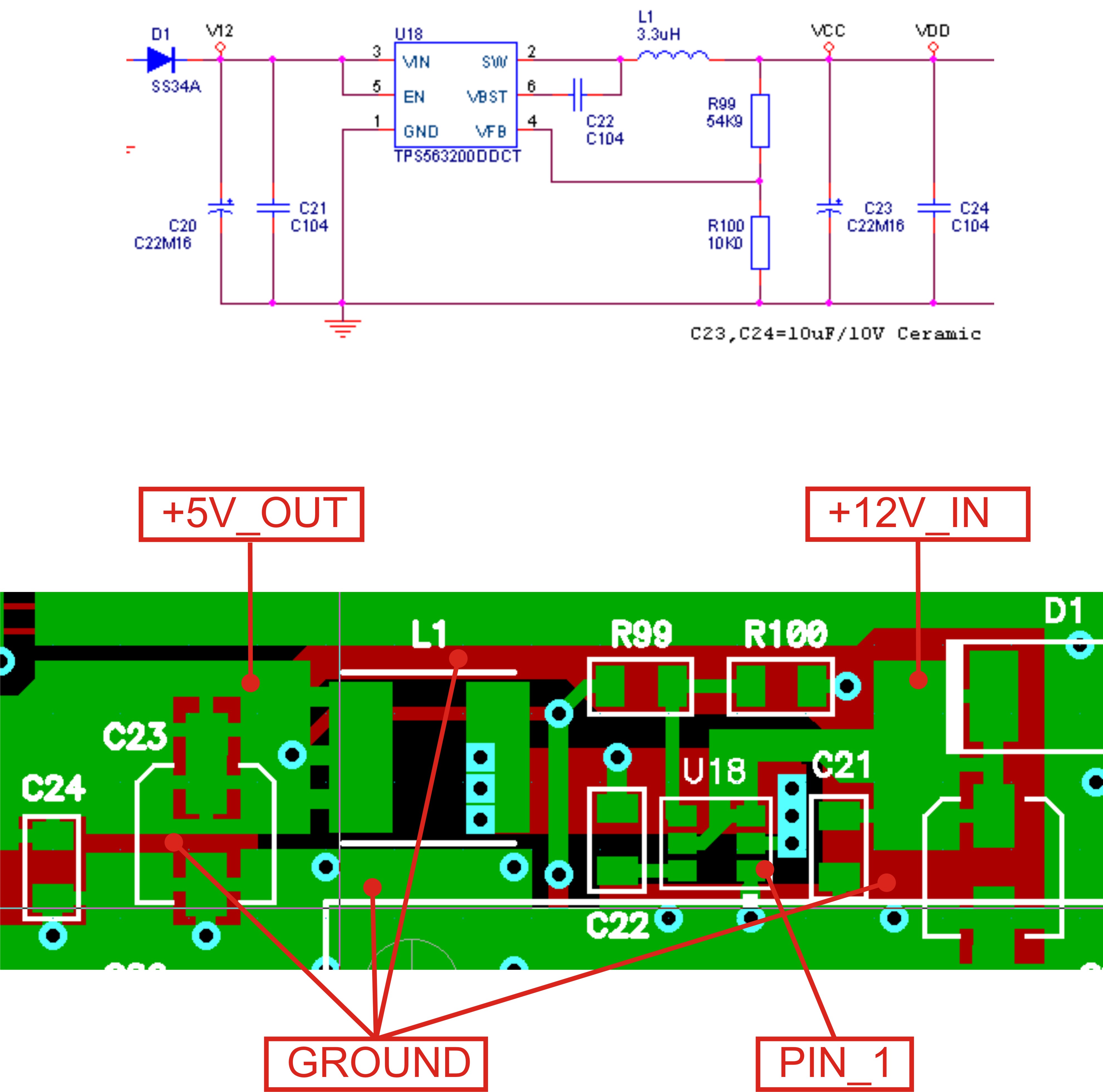
We are using a TPS563200DDCT to get 5V-1.5A from 12V input to supply our board with several MCU's, etc.

Surprisingly, anytime i make a short in the output, the low side mosfet gets shorted.
I did it several times using new parts and the result was always the same. In normal circumstancies all goes ok.
I can't risk the production going out with this issue.

I saw in this forum something related with this issue and someone from texas told to use a different silicon version because the older one has this kind of issue.
We purchased these components for our pre-production at Farnell - ref.2450170. The part is marked with "320".
Please advise about the silicon version and how we can get the "good" ones, if this is the case.

Thanks you

Lino

  • Hi,

    Could you please share the schematic and layout? Let's review them. If the VIN is high and layout is not good, the low side FET would be damage because of the large spike of SW during output short test.

    Shawn

  • Hi, thank you by your quick answer.

    VIN is 12V so is far from the max limit of 17V.

    About the spike on low side FET, i agree, when the high side FET turns off, the current on the low side FET is maximum and decreases lineary to zero(discontinuous mode).

    By the way,

    Component notes:

    - R99 = 54.9K, VOUT=5.1V.

    - C23, C24 = 10uF 10V ceramic multilayer. Inclreasing this values i get less ripple as expected.

    - C104 references = 100n /50V ceremic multilayer

    thx,

    Lino

  • Correction to my previous sentence: "About the spike on low side FET, i agree, when the high side FET turns off, the current on the low side FET is maximum and decreases lineary to zero(discontinuous mode)."

    Independently the mode of operation (continuous or discontinuous), if the controller works as should be, the current that flows through low side FET decreases always to zero.

    Previous sentence refers to inductor current(waveform), that depends on mode of operation.

    Lino
  • hi Lino,
    Normall, the damage issue is difficult to diagnosis.
    You mentioned, the damage only happened when you do the hard short test.
    1. do a transient test: the load from 0 to 3A, check damage or not?
    2. upload the waveform of VIN (test VIN pin) and LX for check
    3. upload the IC image (mark on package) which we can check the IC's date code
  • Hi aswering to your questions;

    1. VOUT: - Varying the load from 0 to 2A (my board consumes 0.02 to 1.5A), i saw several strange behaviours:
    1.1. increasing load from 0 to 0.5A, VOUT increase from 5.12V to 5.47V.
    1.2. Continuing the increase of the load from 0.5 to 2A, VOUT decreases to 5V, more or less linearly with the load variation.
    2. VIN is OK = 12V with aceptable ripple.
    3. As mentioned previously: package mark = (320)

    Additional details:
    VOUT ripple is high... > 400mV.
    The only way to reduce the ripple is by mounting a 10k resistor in series with 100n capacitor, and this series in parallel with R99 of 54.9K.

    Now about the major issue, that is the low side component damage when VOUT is shorted:
    - I solved the issue with an external schottky diode (SS34) to help de internal low side FET.

    Conclusion:
    In my humble opinion, this controller needs a serious revision or maybe you have a new silicon version with no issues(as somebody else mentioned in this forum).

    If a new version is available at Texas, please mail me to explain how can we get them to substitute the old ones.
    Our pre-production continues in stand-by and we are seriously considering changing this controller once for all.

    Regards,
    Lino
  • Hi,

    It seems the feedback resistor is far away from the GND of IC, and the trace is long. Could you please share the waveforms? And what is the part number of output capacitor?

    Shawn
  • Hi,

    1. Output ripple has nothing to do with traces but the wrong type of capacitor mounted. After mounting the appropriate one the output ripple falls to 40mV p/p - SOLVED

    2. For Iout = 2A, the chip temperature rises 25 degrees above the ambient. I do not like this, so, a heat sink welded in the ground plane, the temperature is now just 10 degrees above the ambient - SOLVED

    3. Low side FET blowup when output is shorted: The only way to avoid this issue is mounting a schottky diode in paralell with low side FET. - SOLVED

    4. In addition to the one mentioned above, everything else is the same as mentioned in the data sheet.

    Conclusion: points 2 and 3 are critical what leads me to think that this silicon version needs some attention from Texas.

    Regards

  • One last thing.

    When load is close to 0 Amps i saw TPS563200 working in discontinuous mode with a period of several miliseconds what is incompatible with the output capacitor [22..47uF] as suggested in datasheet, producing a low frequency ripple and several hunderds of milivolts in the output.

    The solution is to connect a 220..470pF capacitor between VOUT and FB pin. In these conditions, TPS0563200 keeps working at high frequency as is supposed to and ripple falls to a few milivolts.

    Input and output capacitors should be MLCC 22uF X5R type.

    About the chip temperature:

    • pcb needs to be a top side ground plane area without solder resist in order to dissipate the heat produced by the chip.
    • The chip should be close enough to this area in order to dissipate the heat (thermal paste between chip and ground area is mandatory to optimize dissipation)
    • A ground plane area in the bottom side with several vias should exist to connect both areas thermally.
    • Both areas should not have any solder resist and these vias should be fill with solder.

    These were the solutions needed to get the TPS563200 to work as it was supposed to... i wonder if Texas did the right tests !?

    Hope those suggestions help everyone with the same issues.

    By my side this thread could be closed.