This thread has been locked.

If you have a related question, please click the "Ask a related question" button in the top right corner. The newly created question will be automatically linked to this question.

LM2842: Won't start - stays at 3.28V

Part Number: LM2842
Other Parts Discussed in Thread: LM25007

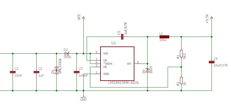
I have a wired behavior with my LM284x. My circuit should output 5.5V.

If I slowly raise the input voltage Vin from 0...8V the output voltage will raise until 3.28V and stay there. The regulator won't start switching. The same happens if I set my PSU to 8V and enable the PSU because the PSU output raises "slowly" to 8V.

If I set my PSU to 8V and plug in Vin — the regulator will start correctly and Vout is 5.5V. 

It seems like the dV/dt has an impact on the function of the regulator. Do you have any idea how to overcome this problem?


Thanks PS: On the Vcc line is a 100u Cap, not visible on this schematic.

  • Hi Thom,

    What is the dv/dt on the input supply? Is the part loaded or not loaded during the startup?
    Also could you try to put a resistor divider between SHDN pin and VIN pin

    Thanks
    -Arief
  • Hi Arief
    Tanks for your reply.

    Arief Hernadi said:
    What is the dv/dt on the input supply?

    With only a load of around 20mA the dv/dt of the PSU is 6V/7ms.


    Arief Hernadi said:
    Is the part loaded or not loaded during the startup?


    The part delivers around 20mA. But if I increase the Load to around 300mA, I have the exact same behavior except the voltage it stays at is a little bit lower (around 2.7V) and the current is under 200mA in this state.


    Arief Hernadi said:
    Also could you try to put a resistor divider between SHDN pin and VIN pin


    I added different voltage divider. As described, the regulator starts if I plug in Vcc directly ("fast" startup). If I now add a voltage divider on the SHDN pin of around 1V, the regulator won't start anymore - it behaves exactly the same as with the "slow" PSU start and SHDN = Vcc (the output stays at 3.3V).
    It seems that the regulator won't start because it is in shutdown-mode...?

    I did some additional measurements:
    I start the regulator (fast startup) - it outputs 5.5V. Now I pull the SHDN pin to 0V - it is in the same state as described above (shutdown state; out = 3.3V). If I connect the SHDN pin now back to Vcc, the regulator stays in this state ant won't start anymore... I would expect it to start pulsing again and output the correct 5.5 V? 


    I also have an older product using this regulator, where it functions correct when I start it with the "slow" PSU. At around 4V the regulator starts pulsing. I did some measurements to compare the two:


    Blue = Vcc, Yellow = SW-Pin   |   first new; second old

    The old circuit it basically the same as the new one, except different values for C104 &L101 and there is not another Regulator (TLV7533) after this one. In addition to that the layout on the PCB is a little different.

    Here is a measurement of the "fast" startup (when I plug Vcc directly in the already running PSU) which works correctly:

    Blue = Output, Yellow = Vcc

    Thanks for your help.

  • Hi Thom,

    Thank you for all the data.

    Yes the part should be turned on again after you pull the SHDN pin low and pull up again to VCC. You should be able to see the switching on the SW node.

    Could we check a couple of things:
    1) Which version of LM2842 that you are using? Is this the X or Y version ? They are different in frequency 550kHz vs 1.25MHz. Therefore your inductor have to be sized properly for the switching frequency that you are using. When you did the comparison test between old design and new design, is the IC have the same frequency?
    2) Is the boot capacitor the correct value? 220nF? What is the value of inductor in the older design?
    3) Also we can take a look at the layout to see if there is anything alarming.

    Thanks
    -Arief
  • Hi Arief

    1.) I am using the X version on both designs. On the old version we used the LM2841X, in the new the LM2842X. For testing purposes I changed the new LM on my PCB to the old one - so I can compare the two better...

    2.) Yes I measured it and it's correct. Here is my old schematics.

    I also did some short testing by changing C_Boot and L to the values of the old schematics but I had the same behavior...

    3.) Here is a part of the layout with some annotations:

    Thanks for your time.

  • Hi Thom,

    I just realize that your input High Frequency capacitor is quite small C3 (100nF), could you try to increase it to 1uF?

    Also could you increase the output capacitor to 33uF ?

    This is one example design from webench

    https://webench.ti.com/appinfo/webench/scripts/SDP.cgi?ID=2881C617E4CCA92D

    Also on the layout you can put the capacitor here

  • Hi

    I think I found the issue. 

    After some additional tests, I noticed that the regulator will start if I apply a short voltage pulse to the Boot Cap. Then I found the document AN-2129 Boot Capacitor Regulation in LM25007 Constant-On-Time (COT) Converter.

    As in AN-2129 described, a regulator won't start if the output is prebias. Figure 2 in this document looks very similar to my measurements posted above. 

    I found out, that a IC on my PCB had an integrated 3.3V LDO which was falsely connected to the 3.3V line. From there the 3.3V LDO feed the voltage back to the 5.5V line resulting in a prebias voltage of about 3.2V.

    After removing the source of the prebias, the regulator worked correctly.

    Thanks for all your help!

    Regards