I built a similar circuit:
http://go.wolfspeed.com/l/101562/2018-07-02/552z75/101562/70670/CPWR_AN24.pdf
With such parameters: Vin=300...400V, Vout=440V, max power 10KW, Cree C3M00651000K.
Slope, SS, CTRL, CHG, DISCHG, CS1 and CS2 circuit is the same as in the document.
I only changed the output and input voltage sensing.
I started testing at ~1KW with a lab power supply (350V input, 440V output, ~200ohm load).
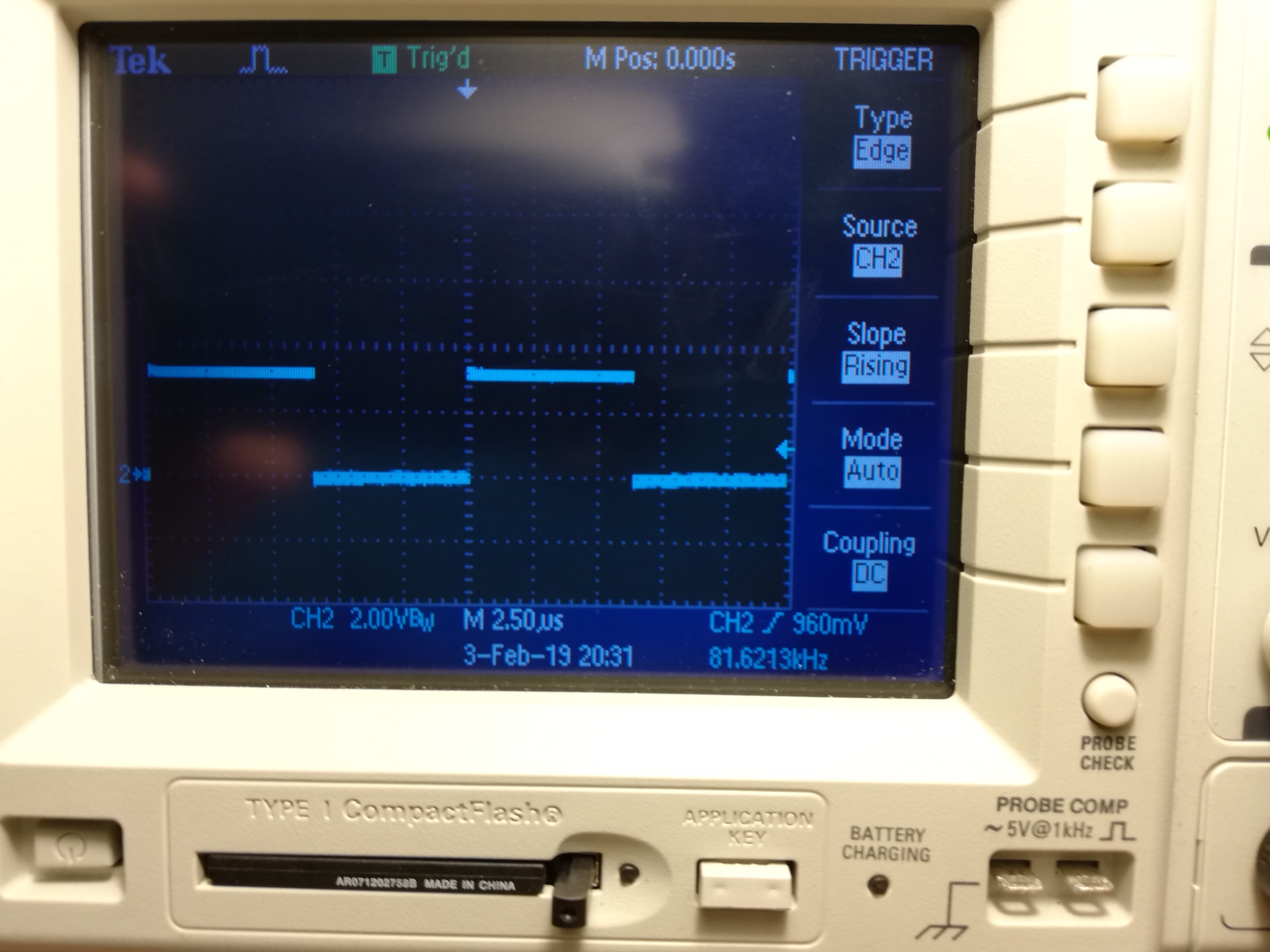
One channel works well, the PWM signal can be measured from the controller normally (from UCC28220 to Cree gate driver module). SiC FET works well on this channel.
But on the other channel I only measure one spike instead of the normal PWM signal. On this channel, SiC FET will only turn on for a moment.
My question:
Is this a normal operation because of the small output load/power?
Or should the two channels work alternately in each case?
Thanks for info!
Regards,
Gabor from Hungary