This thread has been locked.

If you have a related question, please click the "Ask a related question" button in the top right corner. The newly created question will be automatically linked to this question.

TPS65218D0: TPS65218D0 starts to power up then shuts down

Part Number: TPS65218D0
Other Parts Discussed in Thread: TPS65218, , SN74LVC2G07

Customer is using TPS65219D0 in an AM437x application.  We are seeing DCDC4 working to get to 3.3V then shutting down to 1.8V, then reseting the device then restarting this cycle.  I can share a schematic not on the forum if needed.

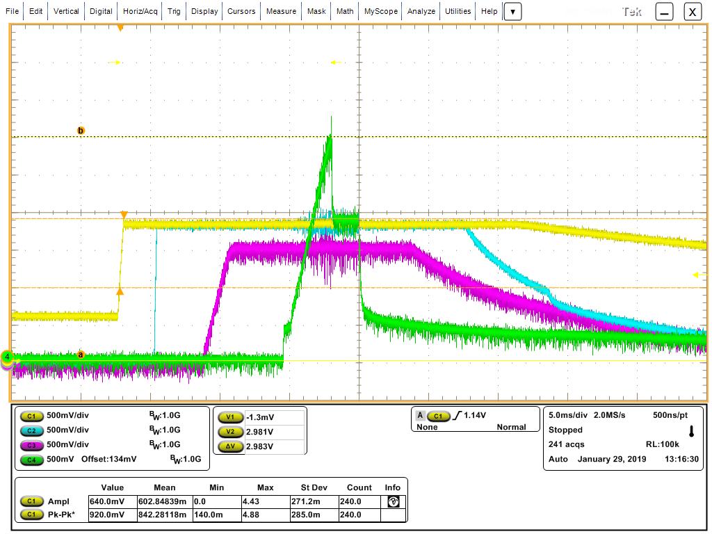
Yellow trace : DCDC6 (V1_8BAT)  at C87

Blue trace : LDO1 (VDD_1V8) at C90

Purple Trace : DCDC3 (VDDS_DDR) at C95

Green trace : DCDC4 (VDD_3V3) at C97

DC34_SEL resistor is set to 12.1K (DCDC3 to 1.35V and DCDC4 to 3.3V)

3.3V rail measures 1.2K to ground and we do not have the current measurement resistors in this design.  Please let me know what you might recommend as we try to troubleshoot this.  Thank you so much,


Will Jarrett

  • Two additional pieces of information. There is the following note in the data sheet:
    DCDC4 Output capacitance should be placed immediately at the DCDC4 pin. Excessive distance between the capacitance and DCDC4 pin may cause poor converter performance.

    My output capacitor (10 uF) is about 5 mm away from the output pin. Is that considered excessive? If so, what would be the minimum capacitance needed at the pin?

    I also isolated the DCDC4 supply from the rest of the board, after the output capacitor, and the supply does regulate at 3.3V.
  • The recommended output capacitance on DCDC4 is 47uF, and the acceptable range on page 12 of the datasheet is 40-100uF.

    The simplified schematic on page 3 of the datasheet shows an additional 100nF capacitor, which is also recommended to filter out higher frequency noise.

    Just to be clear, this question is on the TPS65218D0 and you should be using the -D0 version of the device, which improves performance on DCDC4 vs the TPS65218 (-B1 silicon).

  • We are using the TPS65218D0 part on this design. The 10 uF capacitance is what is closest to the DCDC4 output pin. The 3.3V bus has more than 150 uF of additional distributed capacitance across the board. I changed the 10 uF cap to 47 uF and saw no change in the power up from what is shown in the scope picture in the first post. Also, when the DCDC4 output is isolated from the rest of the board (with just the 10 uF cap) and a resistive load is put on the pin (~3 ohms), the supply powered up as expected. My design is very similar to the AM437x EVM boards, except that I have VDDSVH supplies all connected to 3.3V.

  • Well I think I have found out what was causing my problem. I have 2 SN74LVC2G07 devices on the board that have the power and ground pins swapped. Once I removed these parts, the PMIC powered up properly. Not sure why the supply acted as it did in this circumstance, but it looks like I will be able to move forward.

  • Tim,

    This is great news that you found the root cause of the issue.

    I can't say exactly what occurs when the SN74x device Power & GND pins get swapped, but I am relieved to hear the PMIC is working properly now.

    Let me know if you have any follow-up questions, or simply start a new thread if anything else comes up.