This thread has been locked.

If you have a related question, please click the "Ask a related question" button in the top right corner. The newly created question will be automatically linked to this question.

BQ24620: Battery does not charge

Part Number: BQ24620

I have a custom board designed using the bq24620 to charge a pair of Li ion batteries.

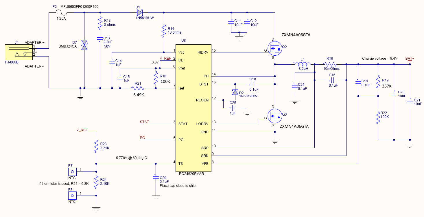
The bq24620 does not seem to be charging the batteries.  I took the following list of conditions from the datasheet.  The schematic is basically the same as the reference design in section 9.2 of the datasheet.

8.3.6 Enable and Disable Charging
The following conditions must be valid before charge is enabled:


- CE is HIGH.
: Tied to Vref. Is 3.3V

- The device is not in VCCLOWV mode.
: VCCLOWV mode is not defined; however, the VCC pin is at 11.8V

- The device is not in SLEEP mode (that is, VCC > SRN) .
: SRN is 6.96V which is less than VCC so the device should not be in SLEEP mode.

- The VCC voltage is lower than the ac overvoltage threshold (VCC < VACOV).
: VCC is much less than VACOV which is 31V

- 30-ms delay is complete after initial power up.
: Charging doesn't start no matter how long the system sits.

- The REGN LDO and VREF LDO voltages are at the correct levels.
: REGN is 6.1V
: VREF is 3.3V

- Thermal shutdown (TSHUT) is not valid.
: Device does not appear hot. Top of case is 26C

- TS fault is not detected.
: TS pin is 1.6V
: Vts is not defined in terms of Voltage but working design example backwards yields

 Tcold is 2.43V
Thot is 1.33V

The STAT and nPG pins are both 3.3V (connected to 3.3V pullups).

The Iset voltage is 0.2V

The battery is 6.95V

The voltage across the 10 mOhm sense resistor is zero (battery neither charging nor discharging)

The voltage at Vfb is 1.51V

The gate and source of the upper MOSFET are 6.95V

Why isn't the bq24620 trying to charge the battery?

  • Hey Steven,

    Can you provide a schematic of your board? You mentioned it was similar to the application diagram. I am curious what is different.

    What is your VBATREG set to through the resistor divider?
    Can you measure the voltage across the sense resistor for charging current?
    Can you measure the VFB voltage?
    What is your ISET voltage?

    In regards to TS, it seems like the charger is abnormally close or in the TS_WARM condition. This is where TS ~ 48%VREF. This cuts the current by 8x which could be significant based on your answer to my ISET question.


    Regards,
    Joel H
  • I couldn't find VBATREG in the datasheet but the resistors in the Vfb connection should give 1.8V at Vfb pin with 8.4V across the battery.

    The original post stated the voltage across the sense resistor is zero.

    The original post stated the Vfb voltage is 1.51V

    The original post stated the ISET voltage is 0.2V.

    The power adapter is supposed to be 12V but we need to survive if a 24V supply is accidentally plugged in.

  • Hey Steven,

    I still suspect that the charger is in T_WARM condition for JEITA. You can try two things you can try:

    1) Force a higher voltage on the TS pin to get out of the TWARM condition.

    2) Set a higher ISET voltage such that the charge current is slightly higher. It is current being set to 1A. In TWARM, charge current = ICHARGE/8 = 125mA. Termination threshold is set to ICHARGE/10 = 100mA. This may be a little too close for comfort and may push the charger into early termination.


    Regards,
    Joel H
  • I made the TS pin change yesterday when I saw your comment.  The TS pin is now at 1.98V which is 60% of Vref and should be in the middle of the normal charging range.  This made no change in how the system worked.  

  • Hey Steven,

    We will need to start capturing waveforms. Can you take a waveform of the PH, BAT+, and VCC nodes as close to the pins as possible. For VBAT, this would be looking at the SRN voltage.


    Regards,
    Joel H