This thread has been locked.

If you have a related question, please click the "Ask a related question" button in the top right corner. The newly created question will be automatically linked to this question.

BQ24650: Polarity and current direction protection

Part Number: BQ24650

Hi,

I am using the BQ24650 to charge a 18V 10AH LiFePO4 battery.

I have a few questions please:

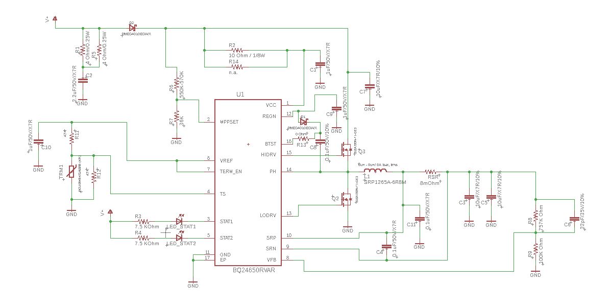
1. I saw in the datasheet that D1 (current direction protection) is located after the MPPSET net but in the EVM it is before. Is there any difference between the two configuration beside taking into account the voltage drop on D1 when calculating the MPPSET voltage divider?

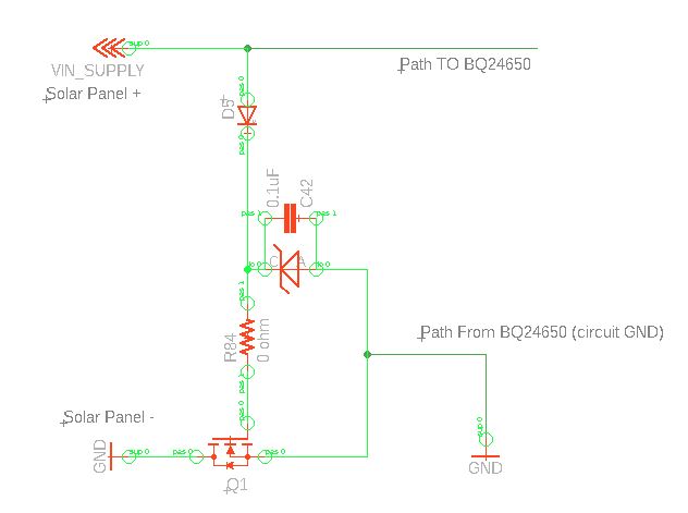
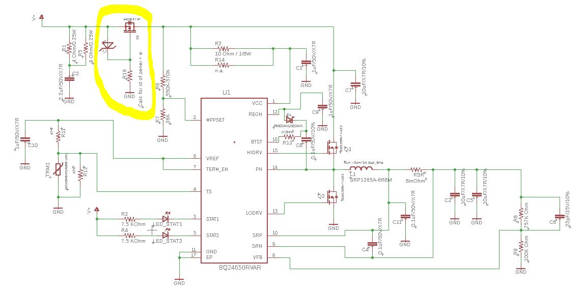
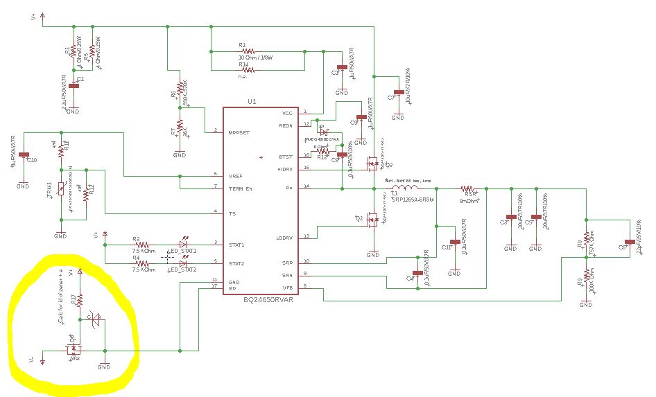
2. Can I add a reverse polarity protection? Low side as in the attachment or High side instead of D1? I ask this because I may need to use a Zener diode to lower the voltage on the NMOS gate (or increase it on the PMOS). Would that interfere with MPP operation?

3. What is the purpose of R5 + C1? (R1, C4 in the EVM)?

4. Can I put the Diode (D1) and/or the reverse polarity protection before R5/C1?

Thanks,

Tomer

  • My mistake about adding the schematic twice.
    They are the same.
  • Hey Tomer,

    1. That is correct. However, the EVM and the datasheet application diagram show the same configuration. On the EVM, MPPSET is connected to a resistor divider from net VIN, same as the application diagram. You want it before the diode such that you regulate the actual panel voltage.

    2. Reverse polarity protection should not interfere with the MPPT regulation loop.

    3. This is an inrush current dampening RC network. This will just prevent your panel voltage from collapsing in the event of a plug in or sudden increase in irradiance/current generation.

    4. I think that should be fine. It shouldn't effect the operation of this circuit.


    Regards,
    Joel H
  • Thank you Joel for your answers, they are very helpful.

    Regarding the reverse polarity protection.

    As I see it I have 3 options:

    1. Schottky diode on the high side

    2. PMOS on the high side

    3. NMOS on the low side.

    Are there any considerations regarding the BQ24650 that should favor one of the designs over the other?

    See attached the 3 circuit options and please let me know what is preferred (if any).

    Schottky diode on the high side

    PMOS on the high side

    NMOS on the low side.

    Thanks,

    Tomer

  • Hey Tomer,

    There are not considerations I can think of. Naturally, we advice just the simple forward Schottky diode in order to also provide reverse current from flowing out of the battery in the even of a short on VBUS.

    But any of these could work for reverse polarity protection. I will say you may want to check the PMOS version; that does not look like a PMOS device to me. The body diode is facing in the opposite direction than I expected, which means I would place my FET in the opposite direction where the source faces downstream.


    Regards,
    Joel H
  • Thanks Joel.

    Yes, you are right about the PMOS.

    Thanks again,
    Tomer