This thread has been locked.

If you have a related question, please click the "Ask a related question" button in the top right corner. The newly created question will be automatically linked to this question.

TPS61194: TPS61194 Output pulses at a slow rate on the anode drive, causing brightness to pulse.

Part Number: TPS61194

Hi,

I have an LCD with 4 string LED backlight, 70mA per string, 37.4 Max Vf, 315kHz switching frequency.  Got the ok from a local TI FAE that my circuit is setup ok.

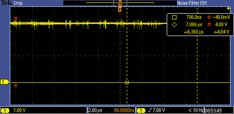
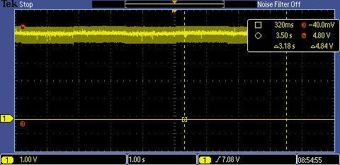
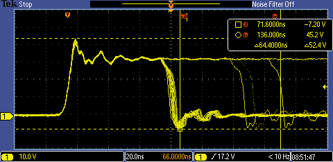
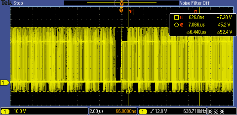
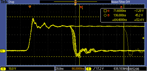
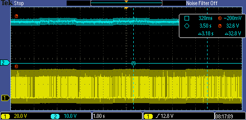
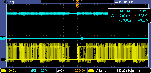
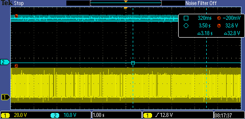
When driving the backlight, I get a 1.4V delta pulse with about a 3.26 second period on the drive signal, which causes the backlight to alternate between two levels of brightness.  This is shown quite readily at any PWN frequency/duty cycle, but seems to minimize around a 10kHz PWM rate.

I have disabled spread spectrum with no change.

FYI, I also added more capacitance directly at pins 1 and 20, tried changing the switching freq to 635kHz (and associated inductor change), changed enable/VDDIO logic levels to 3.3V from 1.8V, with no effect on this issue. Also not specific to one board, I have five of these built up, all exhibiting the same.

Any thoughts?  Scope shot attached.  Thank you.

  • Hi, Mike,

    Proper engineer has been assigned to take a look at this and will reply you soon.

    Due to Chinese new year holidays, response maybe delayed.

    Thanks for your understanding.

    Regards,
    Kenneth
  • Hi Mike,
    Could you please provide the waveforms on "Vin" pin, "SW" pin and the LED output current?
    Regards
    Sean
  • Sean,

    See below.  I can't cut traces right now to check the current to the LEDs, but the set resistor is 40.2k ohm

    5V in, as short and long timescale.  You can see in the envelope how it is seeing similar pulsing feeding back.

    Switch node, at short and long timescales.  I have two captures each to show the different levels of pulsing

    High level

    Low level

  • Sean,

    I received a 61194 eval board today and just hooked it up.

    At 5V Vin input it too has exactly the same pulsing pattern.

    However, since this is decoupled from the rest of my circuitry, I have the ability to increase the input voltage to the part.

    It is very apparent, looking at the backlight, and also the current draw on the power supply that there is a pretty sharp cutoff where this pulsing happens, at less than 12V on the input, and where it stops, when the input is greater than 12V.

    Unless you think this could be some weird manifestation of the LEDs in the LCD, I have to assume it is a 61194 circuit issue.

    This is with the PWM pulled high, for maximum brightness.
  • Hi Mike,
    Could you use some probe to capture the waveform from Vout, Vsw and output current at the same time? I can't get the clear information from your wavefroms.
    Regards
    Sean
  • Sean,

    Here are waveforms Vout and Vsw, at 5V in and 12V in.  Another item to note -- if you look at the datasheet, page 8, I am boosting to about 34V, and at a 5V input, it looks like the maximum boost current at 5V in is only about 200mA, with my strings setup to take 280mA.  Is this possibly a root cause?  While you can operate to 5V, you can't supply enough current at that Vin?

    In any event, as I range the Vin from 5V to 18V, there are various points where the switching is clean and triggers nicely, and others where it goes nuts.

    5V, zoomed out and in

    12V, zoomed out and in

    And here are 2 videos.  First is looking at Vout and Vsw with 5V in (notice pulsing) and then I change to 12V in (pulsing gone and much more stable.

    And worst case pulsing, at 8.5V

  • Page 8 of the datasheet.

  • Hi Mike,
    yes, that should be the root cause, for 34V output and 280mA, take a quick calculation: I_input_avg=Vout*Iout/Efficiecny/Vin=34*0.28/0.85/5=2.24, considering the current ration on inductor, it will trigger the internal current limit, when it trigger the current limit, it will stop switching and the output volatge will drop. then you can observe the pulse pattern. When you increase the input voltage, it will not trigger the current limit. Thanks.
    Regards
    Sean
  • I understand.  Wish I would have noticed this earlier. 

    I cannot use the 61194 in my application.

    I would suggest a note on the front page of the datasheet clearly stating the output current capability is tied to the input voltage level.

    Mike