Other Parts Discussed in Thread: TPS54360B, INA193, TPS54360
Hello,
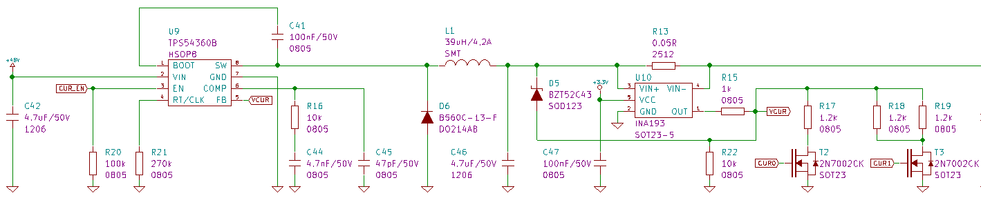
I use a TPS54360B to do a 36-42V 3A battery charger, see enclosed schematic.
T2 and T3 are used to select the output current :
CUR0 = 0 - CUR1 = 0 - Iout = 0,88A
CUR0 = 1 - CUR1 = 0 - Iout = 1,55A
CUR0 = 0 - CUR1 = 1 - Iout = 2,21A
CUR0 = 1 - CUR1 = 1 - Iout = 2,88A
I realize all the measurements with CUR0=1 and CUR1 = 1 (Iout = 2,88A)
The INA193 is used to measure the load current. INA's output voltage is 3V @ Iout = 3A (shunt 0.5R, gain 20V/V).
The voltage divider R15 and R22//R17//R18//R19 is used to attenuate INA signal from 3V to 0,8V (TPS54360 ref voltage).
D5 is a 43V zener diode used to limit the output voltage when there is no load, at Vout = Vz + Vref = 43,8V
The switching frequency is about 300kHz.
The problem is : stability.
The compensation network R16, C44, C45 has been determined from the datasheet, but for a voltage source. I think that the INA introduces phase shifts that are not taken into account, and that disrupt the system. The system is generally stable, but sometimes, during rapid load changes, the system becomes oscillating.
Can you please advise me on the setting of the compensation network, or on other improvements of the system, or is there another more suitable IC ?
Thanks
Thomas