Part Number: LP55231
Hi,
I've put the LP55231 onto my PCB design, and am having issues with getting it working. I2C interface is up and running, and I can successfully force into CP mode and not (with VOUT ADC check working accordingly). However, none of the LEDs are working...! To try and debug I have taken LED2 off of the PCB, but running the LED ADC test I get the same reading for both LED1 and LED2 (0x2a). I've set up registers as follows prior to this test (you'll see LED1 and LED2 differ from others - purely done as part of this debug:
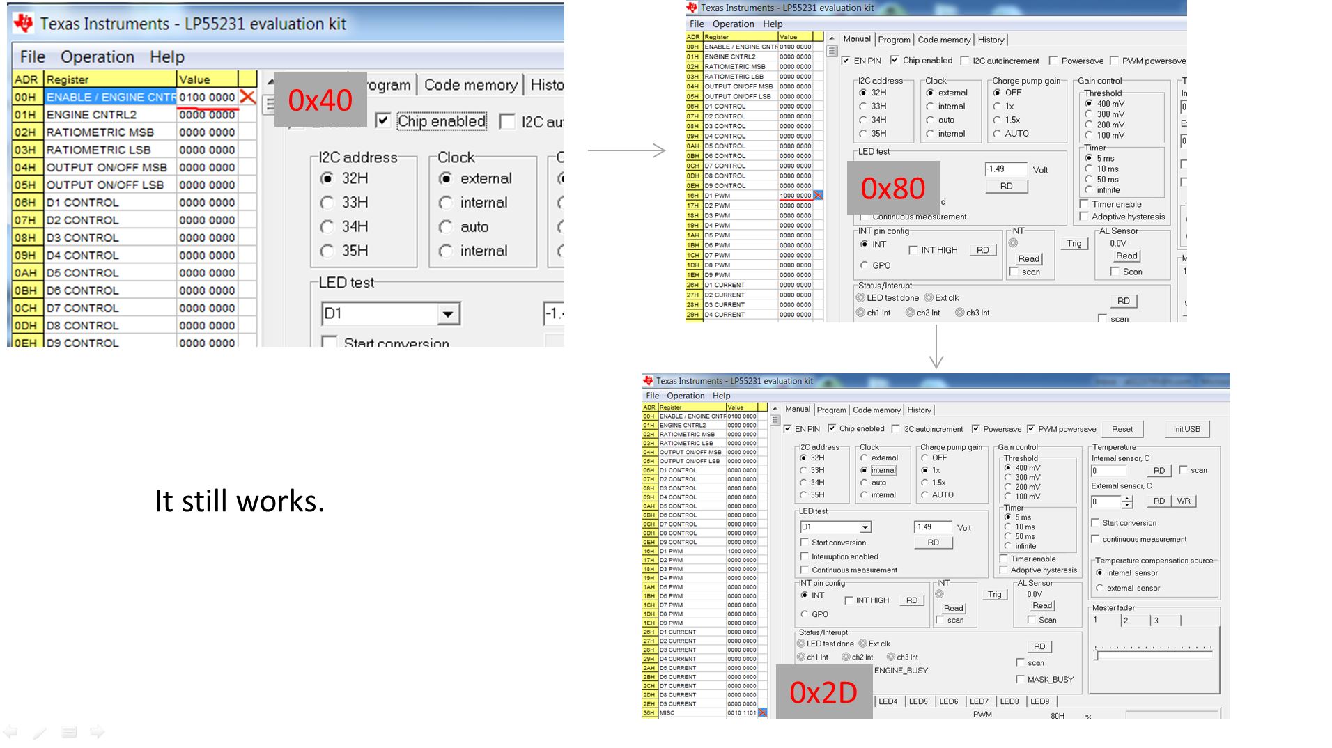
write_led_reg(RegEn, 0x40); //Enable chip (no program execution)
__delay_ms(200);
write_led_reg(OnOffMSB, 0x00); //Turn off LED9
write_led_reg(OnOffLSB, 0x00); //Turn off LED1-8
write_led_reg(PWM1, 0xff);
write_led_reg(PWM2, 0xff);
write_led_reg(PWM3, 0x80); // 1/30 duty cycle
write_led_reg(PWM4, 0x80); // 1/30 duty cycle
write_led_reg(PWM5, 0x80); // 1/30 duty cycle
write_led_reg(PWM6, 0x80); // 1/30 duty cycle
write_led_reg(PWM7, 0x80); // 1/30 duty cycle
write_led_reg(PWM8, 0x80); // 1/30 duty cycle
write_led_reg(PWM9, 0x80); // 1/30 duty cycle
write_led_reg(Current1, 0xaf);
write_led_reg(Current2, 0xaf);
//write_led_reg(Current3, 0x96); // 15mA current
//write_led_reg(Current4, 0x96); // 15mA current
write_led_reg(Current5, 0x96); // 15mA current
write_led_reg(Current6, 0x96); // 15mA current
write_led_reg(Current7, 0x96); // 15mA current
write_led_reg(Current8, 0x96); // 15mA current
write_led_reg(Current9, 0x96); // 15mA current
write_led_reg(OnOffLSB, 0x1F); //Turn on LED1-8
write_led_reg(MISC, 0x0D); //Powersave mode disabled, Charge pump forced off, PWM powersave enabled, forced INT clock
write_led_reg(0x41, 0x8f); //Run LED test on VOUT
__delay_ms(50);
reg_contents = read_led_reg(Status);
reg_contents = read_led_reg(0x42); //ADC result
write_led_reg(0x41, 0xa0); //Run LED test on LED1
reg_contents = read_led_reg(Status);
reg_contents = read_led_reg(0x42);
write_led_reg(0x41, 0xa1); //Run LED test on LED2
reg_contents = read_led_reg(Status);
reg_contents = read_led_reg(0x42);
I'm running through in debug mode and as I say, get expected value for VOUT ADC testing, but 0x2A for both LED1 and LED (even with LED2 not populated). Schematic as follows, and I'm confident the layout matches (although confidence waning somewhat at this point!!). Any idea what might be causing this issue?? This was meant to be so easy...! I've repeated same issue on a number of PCBs, so don't believe it is chip-related.

Thanks.