This thread has been locked.

If you have a related question, please click the "Ask a related question" button in the top right corner. The newly created question will be automatically linked to this question.

UCD9248: How to let the fusion digital power designer know I have a external instrument amplifer to sense output current of the power module

Part Number: UCD9248
Other Parts Discussed in Thread: PTD08A020W

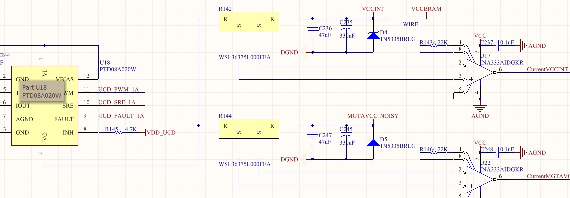
I use ucd9248 to control several power modules. The schemetic is as follows. The current sensing is implemented by a independant instrument amplifer measuring the voltage drop at a very small risistor,

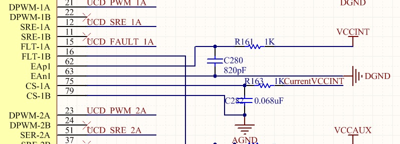
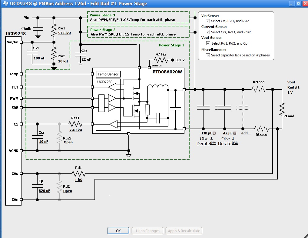
We can see from the following picture captured from the fusion digital power designer. It does not know I use independent instrument amplifier. How to let it know my schematic and allow me to choose the parameter of gain of the amplifier?


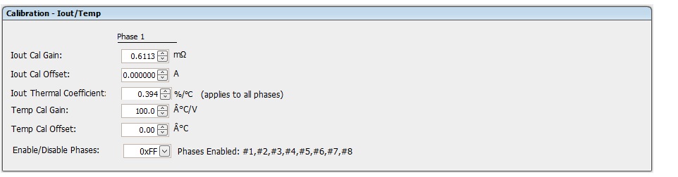
Is it set here? What is the meanning of Iout Cal Gain? Why it uses ohm as its unit? 

My firmware project is also uploaded. Thank you.

  • The UCD9248 current sense signals are intended to come from the IOUT signals on the power modules, like pin 6 on the PTD08A020W module shown in your schematic.  
    One can adjust the gain of the current sense amplifier. Ohms are the unit because the current sense signal is a voltage: A certain voltage represents a certain current. Voltage/Current = ohms.


  • Thank you. xilinx kc705 development board uses the same strategy (with independent amplifier). I follow its strategy. Is it a bad design according to your knowledge?Why.
    If I still employ the xilinx strategy, should I fill the Iout Cal Gain with the real gain value in the Calibration group box?
  • In the third figure of my question. One can add the capacitors to the output rail at the power stage edit page according to the hardware design. Is this setting only used for simulation.Will the mismatch between the setting and reality degrade the performance?
  • Is the following understanding correct? The voltage feedback parameters Rd1, Rd2, and Cp in the third figure of my post must match the real hardware, otherwise the voltage feedback would be misunderstood by UCD9248 and leads to the incorrect output voltage.
    Thank you so much.
  • Hello again,
    There is nothing "bad" about using an external source for the Iout signal, it just adds an extra step in the design, since you will be designing your own current amplifier rather than the one built into the module. You can calculate appropriate values for IOUT CAL GAIN and OFFSET by following the instructions on pg.32 of the User GUIDE linked below:
    www.ti.com/.../sluu490.pdf

    You want the external circuitry (such as the output caps, Rd1,Rd2, and Cp to match your real hardware as much as possible. These values are used by the Fusion GUI to calculate compensation values for your design. It is not just for simulation. See pg. 17 of the USER GUIDE above.

    All the best,
    Xavier