This thread has been locked.

If you have a related question, please click the "Ask a related question" button in the top right corner. The newly created question will be automatically linked to this question.

BQ40Z60: RSOC jumps and full charge capacity low

Part Number: BQ40Z60
Other Parts Discussed in Thread: , BQSTUDIO, BQMTESTER, BQPRODUCTION, BQ40Z50-R2

We have a battery management solution based on the BQ40Z60, having our own custom hardware. Schematic is very similar to the one of BQ40Z60EVM-578, the PCB has passed EMC and is not going to change. The pack is a 2P4S configuration of ICR18650-26F cells.

The protection, gauging, etc parameters have been set up as needed for our application. We are able to complete learning cycles successfully.

The setup functions, but we have two persistent problems with it.

One is simply that the full charge capacity of the pack is showing up low. We usually get something around 4500mAh displayed in bqStudio although it should be 5200mAh (2x2600mAh). Sadly it’s valid and not just displayed incorrectly, manually integrating passed charge gives the same results. Cell Qmax values are always over 5500mAh. I’ve already been playing around with IT gauging config settings, but it did not help. The only way I was ever able to raise full charge capacity to still a bit below 5000mAh, is by raising charge end voltages to (or even a bit above) 4200mV after doing the learning cycle at a 4100mV setting. It seemed like if the learning cycle is already done at a 4200mV setting, we get the same low capacity. Regarding chemistry, there are 2 different IDs for the ICR18650-26F (0137, 1165). Which one is supposed to be used? Do you have any other idea that can cause a problem like this?

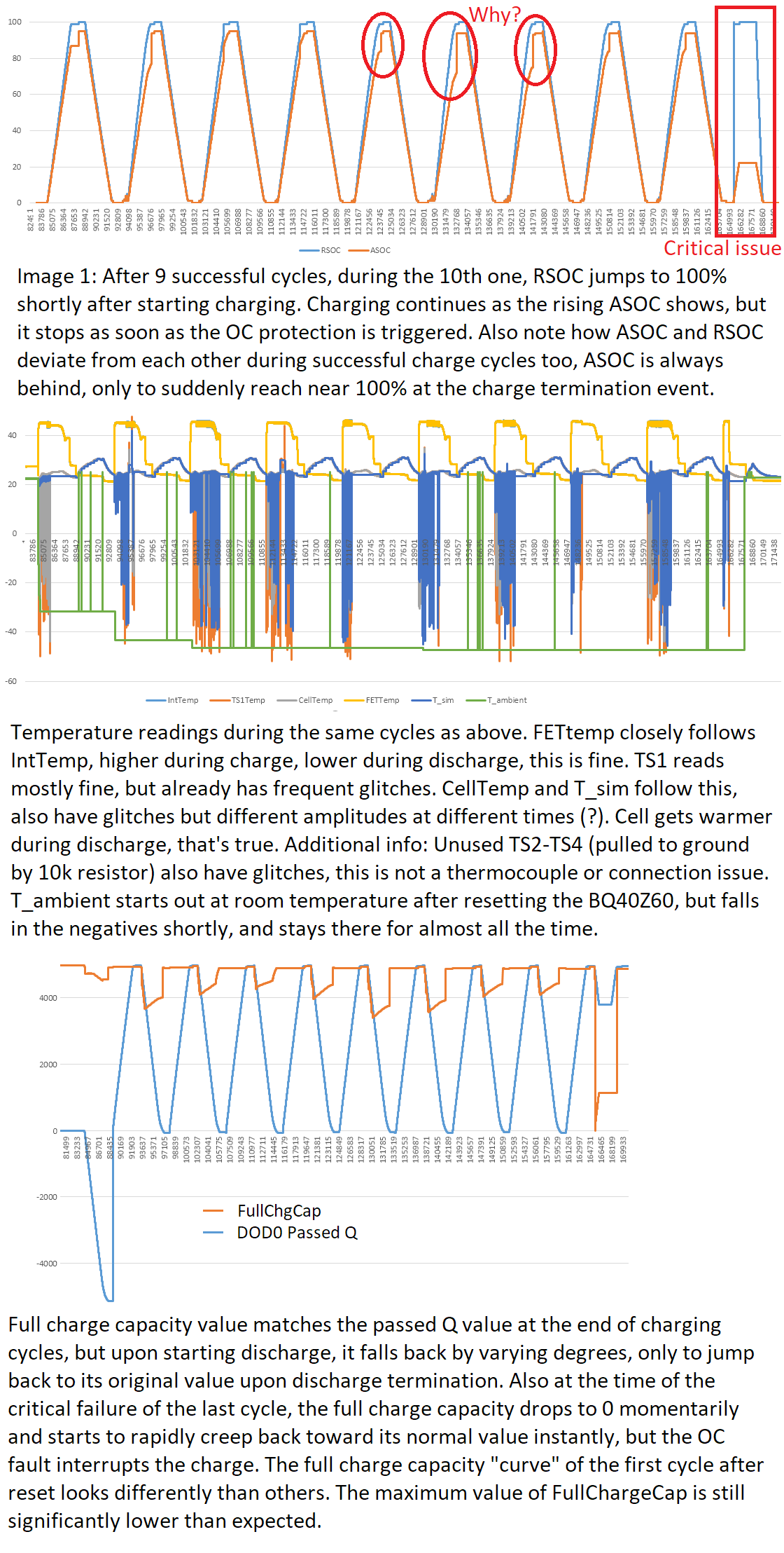
The other issue we’ve observed, is that during charging, RSOC sometimes jumps up a rather large step to 100%. During discharge, gauging is perfect. We could live with the incorrect RSOC display, but this artifact makes the overcharge protection unusable, since charge passed after the RSOC=100% mark is considered overcharge even though ASOC is still lower and climbing. If we set the OC threshold to a reasonably low value, it is going to be triggered and cause a safety status shutdown. Again, playing with IT CFG settings regarding RSOC manipulation solved nothing. Something suspicious I found, is that the T_sim and T_ambient temperature values are often in the deep negatives, -10 to -50°C even though TS1(cell temp) and T_Int reads correctly (around 26°C room temp). And reading through the logged data, the RSOC jump to 100% sometimes coincided with a jump or glitch in some of the temperature values. Any idea for this?

I’m attaching an image to back up what I’m describing. Really looking forward to a suggestion how to solve (or workaround) these issues.
I'm also linking the gg.csv of the setup and a data log sheet if the forum file upload happens to function.

Thanks a lot,

Tamas

  • Can you please send me your srec as well?
  • Hi Batt,

    Thanks for looking into my issue.

    My srec file is here.

    Best,

    Tamas

  • Thanks, I will need at least 5 working days to look into this for you. I will reply back with analysis here.
  • Alright, looking forward to your findings.

    Best,

    Tamas

  • Tamas,

    You have not done your chem ID characterization on the cell. I see that your programmed chem ID is 1210. It should be 1165. Please reprogram it, run a learning cycle and then test it.
  • Hi Batt,

    Wow. I've definitely done that step, although this is already the n-th golden config in the row, so maybe I've missed it the last time?

    Just to be sure, the proper way to create the golden file with the bqStudio is 1) Firmware page - Program the factory default srec 2) Chemistry page - click the applicable row and "Update Chemisrty from Database" 3) Data Memory page - Import and program settings from gg.csv file to device 4) Learning cycle(s) 5) Read out srec 6) This is a question - should I change the Update status value before reading out the srec as some appnotes suggest? Does zeroing the cycle count and qmax cycle count have an effect on operation or are these just logged data for the user's informartion? Or should I zero just one of them?

    Thanks,

    Tamas

  • Yes, to all your questions from 1-5. Setting update status to 0a, if that's what you are referring to allows the end user to send the IT enable command.
    You can zero out qmax and cycle count with no effect on the gauge performance.
  • Hi Batt,

    It's good to know that at least I know how it should be done in theory. Yes I was referring to setting the status to 0a (or to 02 as per some other slua document). Actually we are the manufacturer of the machines the battery will be a part of so there's no different end user. We want to keep the IT gauging on, so in my understanding it means leaving the state at 0e in the golden file is just fine. Right?

    The more important thing is, I've run new learning cycles (3x consecutively) during the weekend. I made sure that the correct chemistry is definitely programmed. I've also calibrated the board using the advanced bqmTester board and bqProduction after applying the gg.csv settings but before the learning cycle as that's a step I've never done before (not mentioned in any documentation as a necessary step) and I figured it might as well help.

    The end result came out tragic, worse than it was before. Full charge capacity is at the same low level as before. Overcharge protection would still kick in if I enabled it. Also, the charge current is now too low and constantly drops during charging, not just at the very end as expected. And the ACFET starts cycling towards the end of the charging cycle. I've recorded the first CHG - DSG cycle, with some graphs on top highlighting the worst items. Could you please check it out? I'm also attaching the corresponding srec file.

    Log file

    Srec file

    To be completely honest, I feel like stabbing in the dark now. I think I have a general understanding about how the chip works in theory, but practice proves me wrong too often. Don't you maybe provide a service where we could mail in some of our hardware and batteries so someone could properly put together the configuration for us?

    Thanks,

    Tamas

  • I'm sorry to know that you're experiencing such issues with learning capacity on your device. The bq40z60 is a BMU, that is capable of charging based on the charger settings in the device. This is unlike any other gauge that would depend on outside chargers to give a voltage and current and then just act when the gauge detected inputs cross certain thresholds. Actually this is a device meant for advanced users and we generally steer people to use the bq40z50-R2 and other gauges as they are more robust.

    If you want to get your packs done by someone else, you can get in touch with Totex or Inventus who are US based pack makers.

    Unfortunately TI does not offer an in house service to make production ready packs.
  • Hi Batt,

    I've explicitly pointed out in my first post that we're not going to change to a different chip, even though I understand what you're saying. I inherited this project from someone else leaving our company and now I'm left with this architecture and I want to get the most out of it.

    A little update since my last post: My full charge capacity is still not the best, but at least the glitches and random issues seem to go away. This is the benefit of correcting a hardware issue, one that actually has been carried over from the bq40z60EVM board. In my opinion, the voltage feedback divider resistors used there (332K / 26.1K) are not well suited for a 4S battery pack. Although we're technically just inside the charger voltage regulation range specified [0.61V - 1.22V], the internal voltage register can't be set properly as its value would have to be above the 255 limit. Now with a [330K / 22K] divider and a recalculated minimum voltage output / voltage resolution pair, the ASOC and RSOC do not diverge from each other during charging, triggering an overcharge status, but stay closely together. Full charge capacity is also a bit higher than was before, still below 5000mAh though, but at least it doesn't vary all that much during a cycle. These are already nice improvements.

    Now one last question you might be able to answer: is there an "upper term voltage" kind of setting somewhere in the charger to set the voltage for 100% RSOC display? Like there's one for the minimum voltage. Now as I've written, now my ASOC and RSOC are the same value almost all the time, but they seem to top out at 90% with a fully charged battery (multimeter verified), and then jump to 100% at charge termination. This is technically not a problem but not nice to show to the user.

    Best,

    Tamas