This thread has been locked.

If you have a related question, please click the "Ask a related question" button in the top right corner. The newly created question will be automatically linked to this question.

WEBENCH® Tools/LM2577: CNC Laser Head

Part Number: LM2577
Other Parts Discussed in Thread: LM3224

Tool/software: WEBENCH® Design Tools

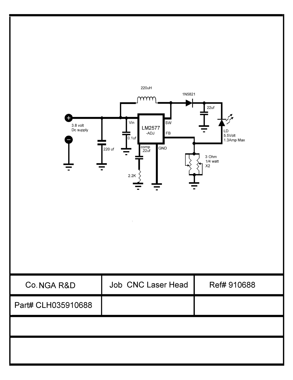
I was wondering if the LM2577 adj would work configured with the load connected to the sense pin. the 2 pots will give me the needed current to ground My target ohm is 1 1/2 watt.


  • Hi Jeff,

    The reference voltage of this device is 1.23V. If connecting a 3ohm resistor to FB pin, the power consumption of this resistor is 0.5W.
    By the way, What's the function of LD? Is it a LED? I'd like to recommend you select other boost converter which has higher switching frequency and much smaller size.
  • those are 3ohm each which gives me 1.5 ohm variable to 0, as I misstated target ohm is 1

    I have been using these already and the only problem I've run into is the output tantum cap shorts out and takes out the chip. tantum caps are good for that.

    I just haven't tried it like that yet (key word yet).    

  • Its a Laser Diode 2 watt perfect for cutting thin plastics.
    I also have a 40 watt 808nm I plan to use later for metal, but that's after I get this thing working properly.
  • I'm open to suggestion's, Just remember I make these by hand, so I need larger footprint then the QFN
  • Hi Jeff,

    I see what you mean. So the laser diode needs a 5.5V voltage? The total output voltage for the LM2577 tantalum cap is 5.5+1.23=6.73V. Could you provide me the laser diode, inductor part number?
    Since Vo is 6.73V, io is 1.3A(max), Vin is 3.8V, the circuit should work fine. When the Vin is on, what's the voltage of Vout, SW? Could you use Oscilloscope to take a picture of SW, VO?
  • So Voltage out is 6.73 (That is 6.73 volts to the diode?¿ ) that will pop the diode. unless the resister burns off the excess? or is something else happening that I'm missing?

    this is calculated at 5%

    Volts In
    3.8 V
    Volts Out
    5.5 V
    Load Current
    1.3 A
    Freq.
    100 KHz
    Vripple
    0.275 V
    Duty Cycle
    47.169811320755 %
    Ipp Inductor
    0.065 A
    Ipk Inductor
    1.3325 A
    Irms
    1.2676388812802 A
    L
    203.19303338171 uH
    C
    22.29845626072 uF
  • Hi Jeff,

    I'm not sure the output voltage because the IC will try to regulate to keep FB pin stable at 1.23V. The Vo is related to the laser diode characteristics. The switching frequency is 52kHz. Why do you say it's 100kHz?
  • oops I got 2 confused

    This is 5%

    Volts In
    3.8 V
    Volts Out
    5.5 V
    Load Current
    1.3 A
    Freq.
    52 KHz
    Vripple
    0.275 V
    Duty Cycle
    47.169811320755 %
    Ipp Inductor
    0.065 A
    Ipk Inductor
    1.3325 A
    Irms
    1.2676388812802 A
    L
    390.75583342637 uH
    C
    42.881646655232 uF

    --------------------------------------------------
    This is 10% and the values are in scope except the Vripple at 0.55V

    Volts In
    3.8 V
    Volts Out
    5.5 V
    Load Current
    1.3 A
    Freq.
    52 KHz
    Vripple
    0.55 V
    Duty Cycle
    47.169811320755 %
    Ipp Inductor
    0.13 A
    Ipk Inductor
    1.365 A
    Irms
    1.2355700438799 A
    L
    195.37791671319 uH
    C
    21.440823327616 uF

    ------------------------------------------------------
    So maybe I should go with the LM3224 ADJ

    Volts In
    3.8 V
    Volts Out
    5.5 V
    Load Current
    1.3 A
    Freq.
    1250 KHz
    Vripple
    0.275 V
    Duty Cycle
    47.169811320755 %
    Ipp Inductor
    0.065 A
    Ipk Inductor
    1.3325 A
    Irms
    1.2676388812802 A
    L
    16.255442670537 uH
    C
    1.7838765008576 uF
  • Hi Jeff,

    LM3224 cannot output 5.5V, 1.3A because it will trigger current limit.

    For lm2557, inductor current ripple could be selected betweeen 20~40%. Have you tried setting R1 7.8kohm, R2 2kohm to get a 6V output voltage like below picture. Then test if the circuit could output 1.3A current at 3.8V vin condition. If the circuit works fine, it should work well if you change it with laser diode.

  • That's how I have it setup right now. (your schematic)

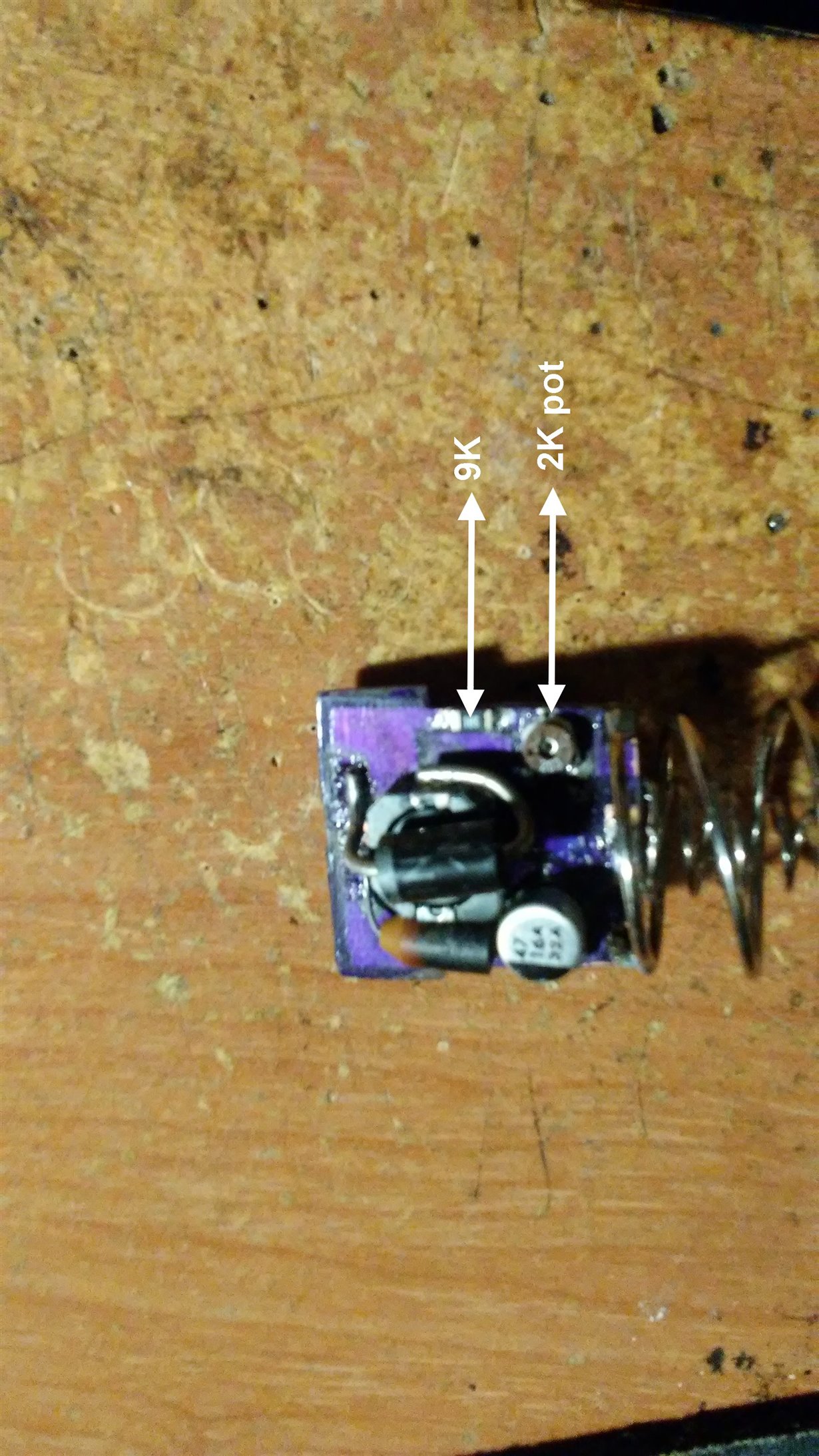
    My R1 is split with a 9K resister and a 2K pot and R2 is a 3K resister which gives me 4.92v to 5.74v

  • what about your MC34063ADE4? It looks pretty good it has the option for an external Transistor
  • Hi Jeff,

    Before choosing another device, let me confirm the problem again with you.
    1. The output capacitor shots out if vin is 3.8V. Does that mean there is no output voltage?
    2. what do you mean 2k pot?
    3. When 9k resistor+2k pot+3k resistor is soldered, do you connect any load?
  • pot = Potentiometer

    The problem with my output cap is tantum don't last and that most likely the fact I had calculated the wrong switching frequency.

    I was using 100khz not 54khz

    I want to step up to a 3.5 watt LD

    https://www.lasertack.com/Media/Uploaded/Datasheets_software/NDB7K75.pdf

  • Why you connect the anode of laser diode to FB pin and cathode to Vout? If I didn't misunderstand, only a current from anode to cathode will activate the diode.
    My suggestion is 1. Build up a circuit like datasheet which could generate 6V. Then connect a load resistance of 6ohm so that load current is around 1A.
    2. Change upper feedback resistor with the laser diode. Make sure the cathode diode is connect to FB pin.

    From the datasheet you provide, the operating voltage is 4.3v when if=2.3A. LM2577 cannot generate such a big current because of the switch current limit.
  • sorry for the late reply sometimes work consumes all my time.

    yes I have been looking at others like your MC34063ADE4 and using it to switch an external 5amp transistor


  • the reason I am looking at others is that I could use the HL63193MG 638nm L.D. datasheet as you san see it is 2.6 volt 1 amp max

    and the MC34063ADE4 is up or down so 1 chip 2 slightly different p.c.b. layouts and a few different parts. Simple sounds great to me.

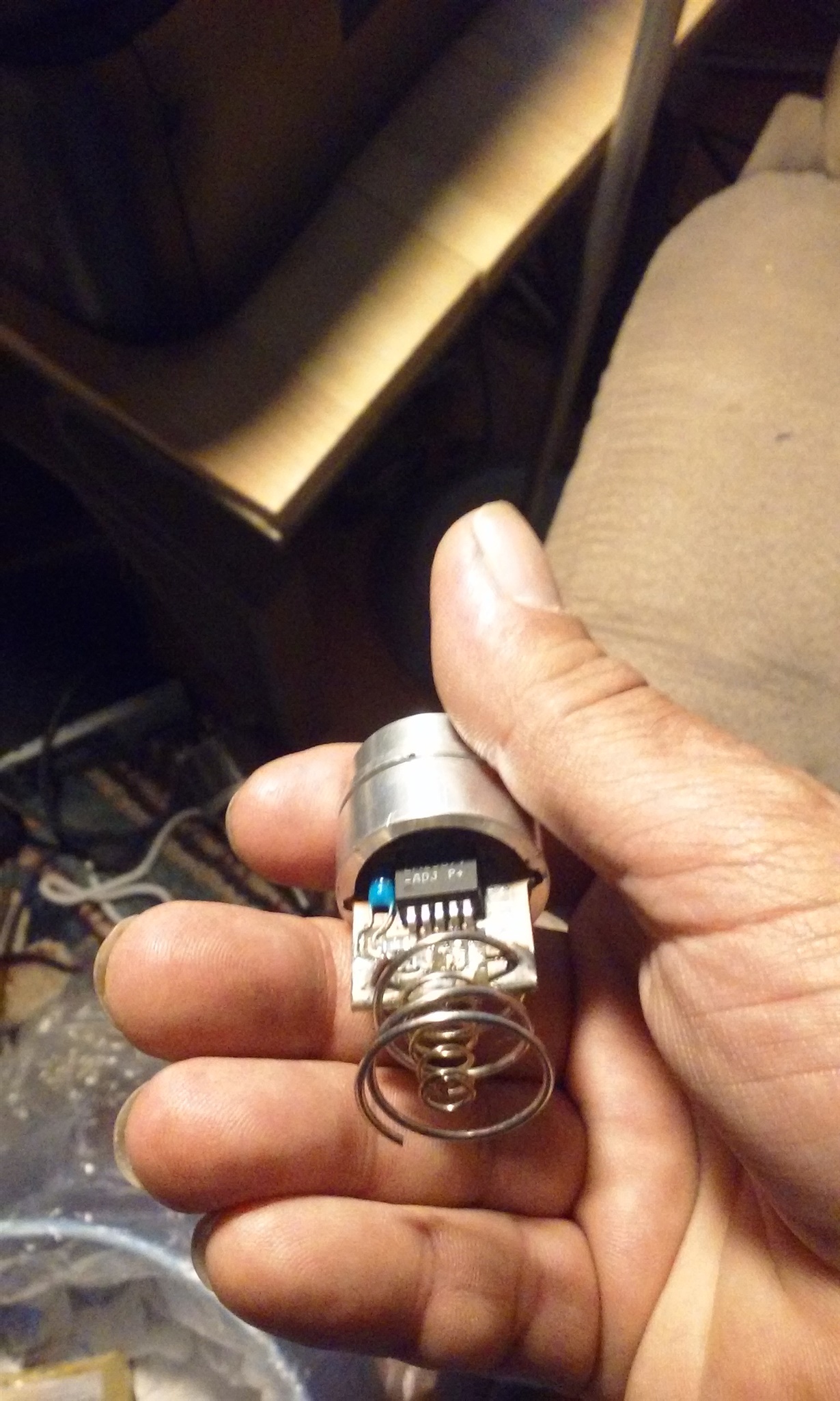
    this way all I need to do is change out the head (the hole part as in the picture on page 1) to cut different color plastics for easy change over..

  • "Feb 22, 2019 10:35 AM

    In reply to Jeff Lampe:

    Why you connect the anode of laser diode to FB pin and cathode to Vout? If I didn't misunderstand, only a current from anode to cathode will activate the diode."
    ----------------------------------------------------------------------------------------------------------------------------------------------------------------------------------------------------------------
    If I have the LD in the schematic backwards? please excuse I am a little dyslexic let me know and I'll be glad to fix it.
    I have been using the lm2577 as in the datasheet schematic, application specific values calculated at the wrong frequency which explains why I'm frying the output cap. 
    They work beautifully until the output cap goes..  
  • Hi Jeff,

    How about your circuit using MC34063ADE4 now?
    I don't think it's because you calculated the wrong frequency cause the output cap shorts out because frequency only may affect output voltage ripple and switching current ripple.
    I'll close this thread. You can post new thread if you are deciding to using MC34063ADE4.