This thread has been locked.

If you have a related question, please click the "Ask a related question" button in the top right corner. The newly created question will be automatically linked to this question.

BQ76940: Charging Current and Load Connections

Part Number: BQ76940

Hi,

I am designing a BMS for 13s Li-ion pack (48.1v). Kindly help me understand two things - 

1. Is charging supported by BQ76940? How will the cells be charged?

According to my understanding, an external supply will be required to charge the cells but I don't see any options to set the charge current. Charging and balancing are two different things. Many settings are available for balancing but for charging, only a CHG MOSFET is available which I believe will cut off the supply from external charger in the event of OV on any cell. Kindly shed some light on cell charging. Can charging be controlled via BQ76940 or do I need an external balance charger to charge the battery pack?

2. Can cell balancing be active during charging and discharging both?

As far as what I have understood, the battery pack is always connected to the BMS and can keep the BMS powered on always (BMS will be constantly supplied 48.1v by the pack). Since the BMS will always be on (assuming no faults occur in the battery), I can program the MCU to balance the cells continuously, be it during charging or discharging. Is my understanding correct? 

3. Balance Current: How much? Effects of high/low balance current?

How to decide the balance current value? I have a 1kWh pack (13s7p pack consisting of 3.7v,3000mAh Li-ion cells). I have referred to a TI design and the balance current is set to 28.7mA. Assuming my cells to be matched closely within 1-3%, what should I set the balance current to? What are the repercussions of too high balance current? What factors to consider while deciding its value?

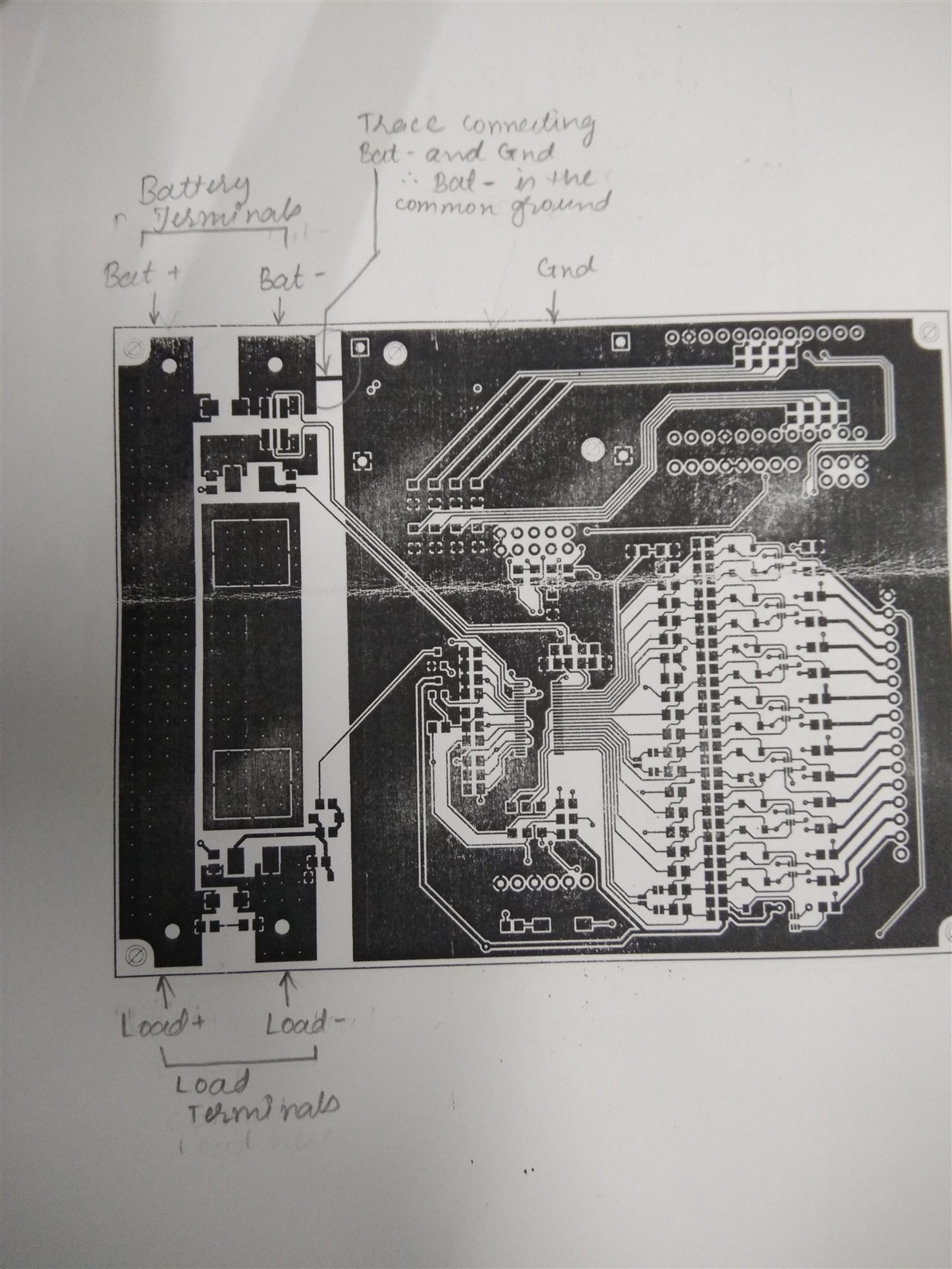
  • 4. Is Load- and Bat- shorted? (refer image connection.jpg)

    The EVM board had two pairs of terminals - PACK terminals and BAT terminals. I understand that across one set of terminals, LOAD will be connected and across the other set BATTERY terminals will be connected. Hence I call these 2 sets as (LOAD+, LOAD-) and (BATT+, BATT-). My question is, is the LOAD- and BATT- shorted? In some designs I have noticed that the LOAD- is not connected to GND . (refer the image CHG DSG section.png)

    Connection.jpg

    CHG DSG section.png

  • Hi Pranit,
    1. The bq76940 allows charging but it does not provide it. Yes, and external source is required to charge the battery. The bq76940 allows something to read the cell voltages, configure a threshold, and if the ADC is enabled and the voltage exceeds the threshold for the time the bq76940 will turn off a charge FET if the board is so designed. It will also allow a host MCU to control balancing.
    2. Balancing may be operated during charge or discharge as determined by your MCU. Many BMS systems will only balance during charge since that is when current is coming into the battery. Others will balance during idle since that is when there is the least IxR drop on the cells and the best measurement of the voltage is available, even though the balancing dissipates some energy. Balancing during discharge is rather unusual.
    3. Balancing provided by the bq76940 is dissipative. In low cost systems the resistors are on the board near the cells, so there is a limit of how much power you can put into the board and a decision of how much you want that to heat the cells. If you have a larger system and can locate the balance resistance away from the cells higher current may be suitable. Consider the possible mismatch as you are thinking. Generally it will be better for the battery if the cells are matched before assembly rather than expecting the BMS to balance the cells quickly. Also consider how much time will be available for balancing. If a system balances only during charge and charges quickly infrequently, you will need a high balance current. If the system balances during idle time and spends a lot of time idle, it will have a long time to balance and current can be low. If you have matched cells you only need to balance for mismatches during operation, see the offset currents in the bq76940 data sheet, consider differential heating effects in the pack and its possible effects on self discharge. Hotter cells will self discharge more and the others will need to be balanced down to match.
    4. Load- and BAT- are not shorted. The bq76940 uses low side current sensing through a low value resistor. On the EVM low side protection switching is used, like your schematic section. So Load- (or PACK-) and BAT- can have a large voltage difference during protection. On the EVM the VSS for the bq76940 connects to the BAT- net so that large currents push the sense pins positive rather than negative, the pins have a larger positive range. On the EVM BAT+ and Load+ (or PACK+) are the same net.
    On other designs high side switching is used to make ground referenced communication more practical. In these systems BAT- and Load- are still not shorted since the sense resistor is between them. It is a small resistor, but important.
    The thin trace between BAT- and GND connects the signal reference (GND) for the ICs and circuitry to the BAT-. One view of electronic circuit design which is followed with the EVM is that high currents should be directed away from low level sensitive circuits. That is forced with the net-tie or narrow connection such as you have shown. It does not need to be so small, but high current should not flow through the low level ground causing reference level differences in sensitive circuits.
  • @WM5295 this cleared all my doubts! Thanks for the prompt reply :)