This thread has been locked.

If you have a related question, please click the "Ask a related question" button in the top right corner. The newly created question will be automatically linked to this question.

LM5176-Q1: High Power Consumption with no load

Part Number: LM5176-Q1
Other Parts Discussed in Thread: LM5176

Hello there.

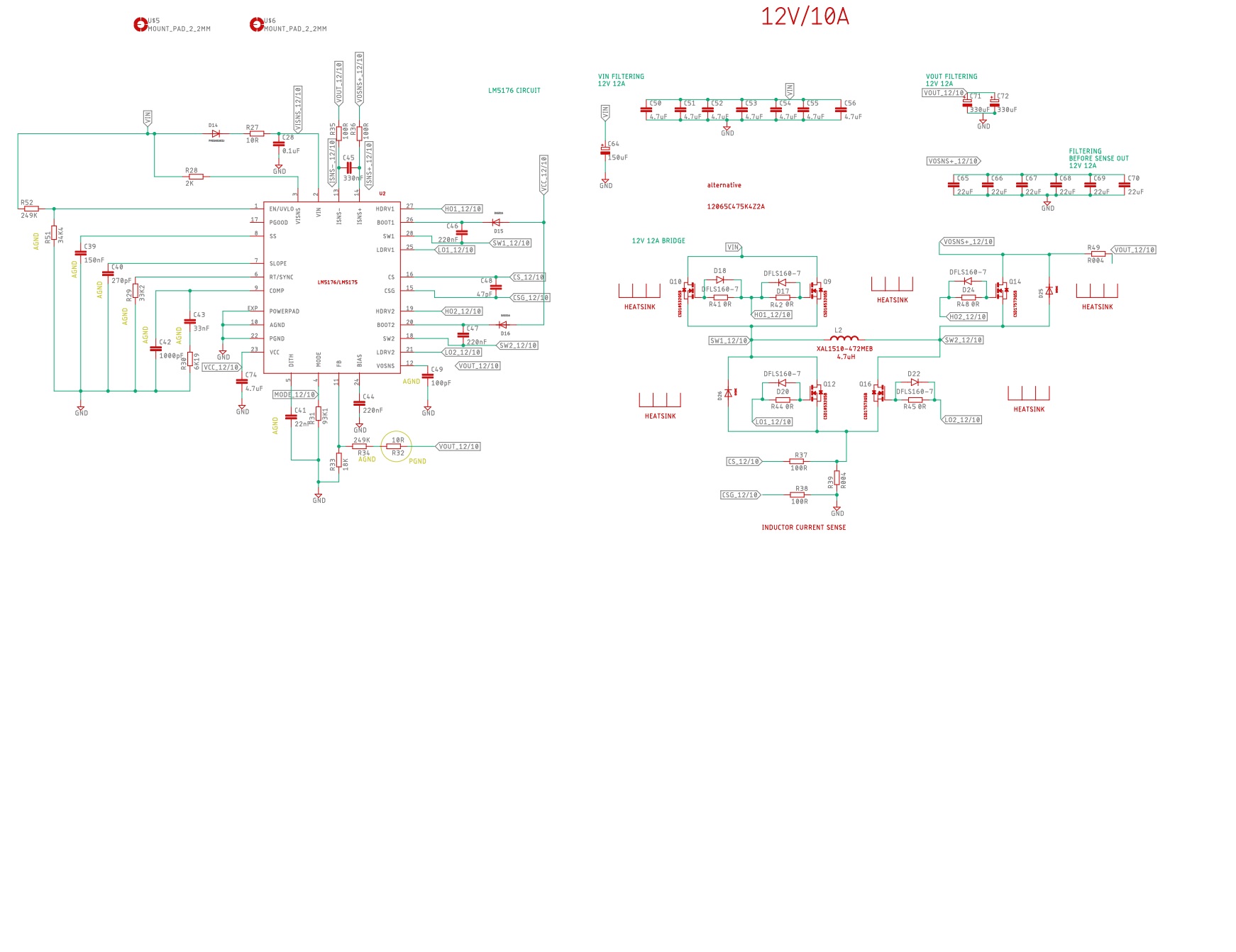
We have built a buck-boost converter with LM5176 based on the evaluation board designs, with 12V and 12A output from 10V-24V inputrange. The circuit worked as expected with low ripple and good transient response.

The problem is when we powered it up with low current limit (around 20mA), from the bench power supply, while the inrush current for starting was about 200mA leading to a hiccup behavior of the bench power supply. The result is that the circuit is somehow damaged and we can figure out how. Although the output voltage is correct and all the gate signals are acting correctly, there is a significant higher consumption than before with no load. With 24V input it shows around 135mA consumption.

We have already changed the controller IC, input capacitors, upper and lower MOSFETs and inductor but nothing seems to correct the problem. Measurements in boost capacitors do not show anything abnormal and diodes are measured correctly. 

We haven't tested yet the circuit with load, after the fault occurred.

Any help on what to suspect for the excessive power consumption would be helpful. 

Thank you in advance.

  • Hi Nikos,

    Thank you for using the LM5176. 20mA limit sounds too low. Anyway, would you please show your own schematic for a review?

    Thanks,
    Youhao Xi, Applications Engineering
  • Hi Nikos,

    Any update? Or the issue is resolved and I can close this thread here? You can reopen it by following a new post.

    Thanks,
    Youhao Xi
  • Dear Youhao

    thank you for the fast response and sorry for my own late one.

    The circuit performs as it should under load. I am attaching here the circuit's schematic.

    Thank you for your time

  • Hi Nikos,

    I reviewed your schematic and I did not find anything being the obvious cause of your problem. I do see your input having an electrolytic capacitor. If your input cable between your power source and the LM5176 input is long and not twisted, you may introduce some parasitic inductance in the input line, and once your input source drops owing to current limit, there would be outrush current from the LM5176 back to the input source, and the the voltage at LM5176 circuit input can swing to negative, causing some damage to your input electrolytic and hence increasing the leakage current.

    Thanks,
    Youhao Xi, Applications Engineering
  • Hello Youhao

    We did change the electrolytic capacitors. One was found faulty. The only thing that was left unchanged, after the fault, were the ceramic capacitors, both input and output, but I find unlikely to be the source of the leakage.

    To close the thread since I understand that is difficult to figure out the problem if it is not that obvious, how do you protect in a final product that this cannot happen due to false operation. Is reducing any parasitic inductance in the input adequate measure or there are more applicable solutions.

     I would increase the soft start time but, if I have understood correctly, overcurrent response also depends on the soft start. Currently is set to 25ms. Can I increase it with compromising overcurrent responsiveness.

    Thank you.


  • Hi Nikos,

    Thank for the discussion. The good practice is to make sure your input cable is twisted to minimize the inductance, and the cable is as short is possible. You may also consider to put a diode across the electrolytic, with its cathode on the positive side, and Anode on the negative side, then your capacitor will be protected against negative voltage damage. This may only needed during your evaluation phase and you can decide not to populate it in mass production is the negative voltage condition can be excluded during field applications.

    You can increase the soft start time to limit the inrush current. But note that it does not affect the inrush to the input capacitor bank.

    Thanks,
    Youhao Xi, Applications Engineering