This thread has been locked.

If you have a related question, please click the "Ask a related question" button in the top right corner. The newly created question will be automatically linked to this question.

TPS62748: Buck not switching from PFM to PWM mode

Part Number: TPS62748
Other Parts Discussed in Thread: TPS62808, TPS62801, TPS62743

Hi,

I am using the TPS62748 as a power supply in one of my designs. I am using an MCU that draws 4 mA so starting the MCU is no problem. However, from time to time I activate another component in the design which is also connected to the buck converter. This component momentarily consumes 70mA. I then see that the buck converter can't switch from PFM to PWM mode, so this component never starts.

Obviously I have done something wrong.

The output capacitor of the buck is 10uF (same as input capacitor). Total load capacitance on buck (including output capacitor): 18.7uF. I don't have a good estimation of the PCB capacitance. I have used the following inductor:

1285AS-H-2R2M=P2 from Murata.

Could you please tell me where to find more information about what parameters affects the switching from PFM to PWM mode so that I get a starting point when searching for the root cause in my design?

Thank you!

  • Hi Joseph,

    What makes you think the part doesn't switch modes? Is this an issue for your application? Are you using 1.2Vout or 1.8Vout? What is your Vin?

    The change from PFM to PWM happens automatically and occurs when the inductor current reaches 0 (CCM/DCM boundary). From figures 15 and 17, you can see that the change occurs when the frequency starts to flatten out--around 150 mA from 5Vin to 1.8Vout, for example.

    You are likely still in PFM at 70 mA load. This is ok for the device.
  • Hi Josefin,

    Are you still having issues?
  • Hi Chris,

    Thanks for your feedback!

    I have realized that there was no problem switching between PFM and PWM mode, as you stated, at 70mA the buck is still in PFM mode. The problem I had was that the ripple of the buck output voltage (which is as specified in the datasheet) was too much for the sensor I was using and it started misbehaving.

    I have found some minor discrepancies in the PCB layout compared to your recommendations that I will apply and hopefully that will reduce the ripple a little bit. However, do you have any other suggestions how to minimize the voltage output ripple? Would it be possible to use a larger inductor? In the datasheet you only specify 2.2uH.

    Best Regards,

    Josefin

  • Hi Josefin,

    Thank you for explaining. Can you post a waveform of the measured ripple and your ripple requirement?

    The TPS62808 has a forced PWM mode, that you can control with an MCU. While we continue to debug your TPS62748, I wanted to give you another option as well.
  • Hi Chris,
    Thanks for the tip about TPS62808. Unfortunately, low quiescent current is very important in my application, so the TPS62808 is not really an option.
    I will come back with ripple requirements, but I need a little more time.

    Best Regards,

    Josefin
  • Hi Chris,

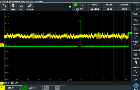
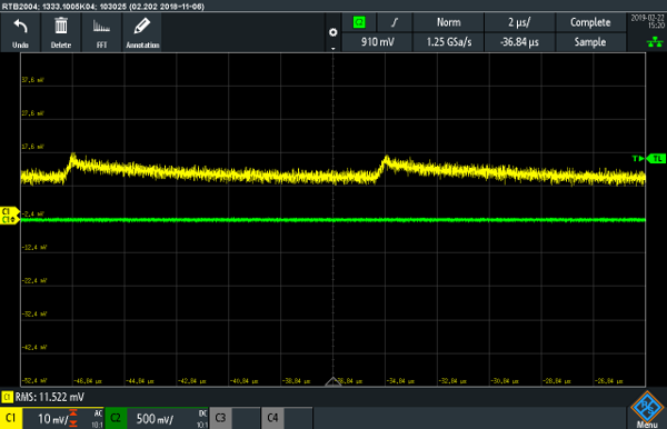
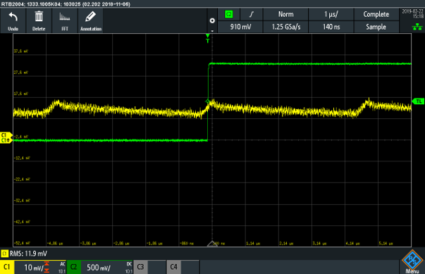
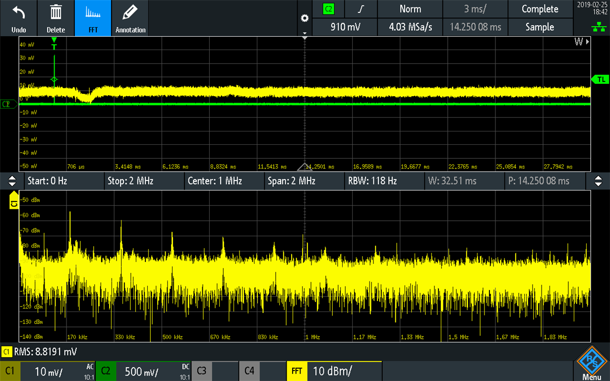
    We have now concluded that our ripple requirement is 1mV. I understand that that is not possible with a buck regulator, but still, if there is a way to get down to 5mV, then that would still be very helpful. Maximum current consumption will be 100mA.

    Below are three pictures of the waveforms showing the ripple. The oscilloscope is AC coupled during the measurement. 

    Below is a waveform of the ripple with 50us resolution on the time axis:

    Here is a zoom of the ripple with ~83kHz frequency. 2us resolution on the time axis. 

    And here is a zoom of the ripple with ~217kHz frequency 1us resolution on the time axis. 

    Below is the FFT of the ripple:

    Best Regards,

    Josefin

  • Hi Josefin,

    Thanks for posting your ripple requirement. It is nearly impossible to get below 1 mV ripple while maintaining low Iq (operating in PFM).

    So, we made this reference design last year to show how to achieve this: www.ti.com/.../TIDA-01566

    By using a low Iq DC/DC followed by a low Iq LDO, you can have both low Iq and low noise.

    You could replace the TPS62801 in the above design with the lower Iq TPS62743.
  • Hi Josefin,

    Would this reference design give what your system needs?
  • Yes it did!

    Thank you very much!

    Best Regards,

    Josefin