This thread has been locked.

If you have a related question, please click the "Ask a related question" button in the top right corner. The newly created question will be automatically linked to this question.

LM5175: UVLO schematic check

Part Number: LM5175


Hi Guys,

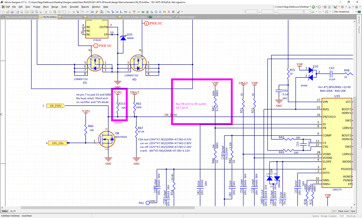
My customer is changing the EN/UVLO settings away from from 3.3V (10K) pullup to

VBAT and a divider of 205K and 47.5K.


Do you see any issues/concerns  with these values?

math is on the sheet below.

Really concerned with the value for crank (below).

Does this fall into line or do I need a higher value?

Thanks,

Brian

  • Hi Brian,

    I believe they want the circuit continue to operate when Vin drops to 6V, right? The calculation is correct for UVLO rising edge, but once the circuit is enabled, there will be 5.5uA current flowing out of the EN/UVLO pin, which lifts the UVLO voltage higher for hysteresis. The

    To design for worst case such that the circuit can operate with a cranking voltage of 6V, they should choose R67=53.6k. This is to make sure you still have the UVLO voltage >1.29V when VIN=6V, to guarantee operation. For the worst case, consider 2 the min UVLO hysteresis current and highest UVLO threshold (1.29V). Also consider 2% resistor variations, as well as total including the initial tolerance and variations due to temperature.

    Thanks,
    Youhao Xi, BCS Applications Engineering