Other Parts Discussed in Thread: LM3409
Hi all:
I have the below circuit, that it was make following the advises of the LM3409 datasheet and some of my older post here (as adding the dieode between UVLO and PWM)

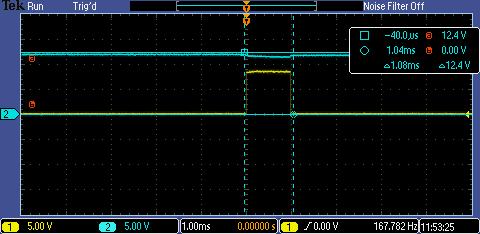
This design should give a pulse of 1 ms pulse at 25 Hz, with 5 A to a string of three leds, giving more than 10 V between string terminals.
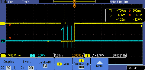
I have some problems here: First of the problem is that I still have the issue of "shutdown mode". The output pulse have the same behaviour that before. Making some test, output is delayed, no matter the diode is on the circuit or not. in the grafic below, you can see yellow line (pulse) and blue line (output pulse), and see how the output it is delayed. As I said, no matter is the diode or not

Secondly and probably more important. From the voltage of the output and the led datasheet, I would say that output pulse is far from being 5 A, and it Will be closer to 2.5 A. I dont know exactly why, maybe I am requiring too much to the external source or something is wrong in the values of the circuit.
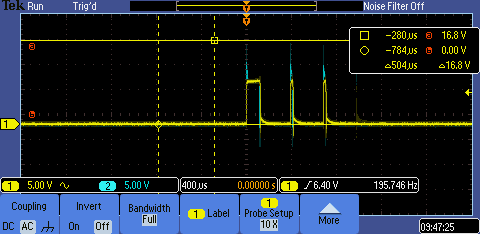
Anyway, I want to recalculate everything to get 2 A and 9 V, because 5 is too much for my application. When I made calculation, I choose 0.1 ohm in Rsns and 5k6 in Roff to have about 9 V and 2A. i think this is more or less correct. Doing that, I have the following output pulse (it is the yellow line)

In theory my clculations are good, so I dont know what is happen. I have making some test, changing the Rsns of the circuit, step by step, to see the behaviour of the theoretical current against the real current and when I goes up over 0.06 ohm, the behaviour is as the behaviour above.. Below 0.06, is as the first graph.
Could it be the same problem as the problem I have with the delay between the output and the pulse?
Someone could help?