Hi experts,
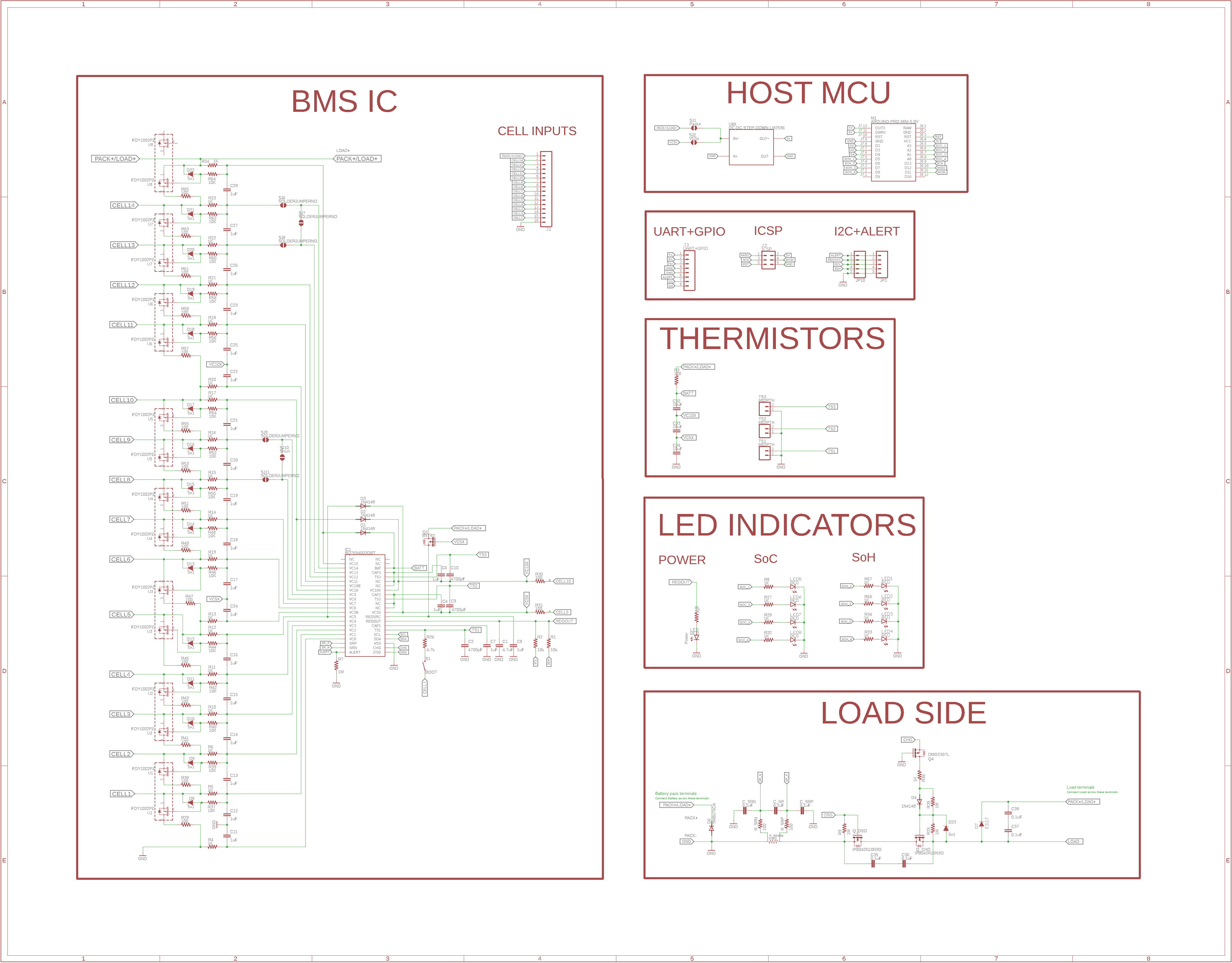
I have made a 13s-15s BMS using BQ76940 (3.3v version). I’m fetching the cell voltage data from the BQ using atmega328p. The ckt has jumper pads which can be used to configure the board for 13s-15s battery configurations.
Kindly check the schematic
There are 6 jumpers pads in total – SJ6, 7, 8 and SJ10, 11,12
SJ7 shorts VC13-VC14
SJ10 shorts VC8-VC9
So the jumper states corresponding to 13-15s config are
13s: SJ6 open, SJ7 close, SJ8 open
SJ10 open, SJ11 close, SJ12 open
14s: SJ6 close, SJ7 open, SJ8 close
SJ10 open, SJ11 close, SJ12 open
15s: SJ6 close, SJ7 open, SJ8 close
SJ10 close, SJ11 open, SJ12 close
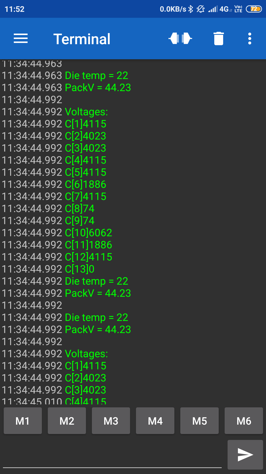
I’m using the board in 13s configuration. I’m using Bluetooth for debugging, pushing the data on a Bluetooth terminal on my phone I get the following output. Kindly check the output image(black background with green text)
C1-5 are reported perfectly
C7 is reported perfectly
C12 is reported perfectly
Rest all cells’ voltages are incorrect. In my ckt, VC0 is connected to gnd, VC15 is connected to BAT+. So the cell connections are
C1: gnd-VC1
C2:. VC1-VC2
C3: VC2-VC3
C4: VC3-VC4
C5: VC4-VC5
C6: VC5-VC6
C7: VC6-VC7
C8: VC7-VC8
C9: VC9-VC10
C10: VC10-VC11
C11: VC11-VC12
C12: VC12-VC13
C13: VC14-VC15
I checked the datasheet and the sample ckt shows VC0 is grounded. However in TIDR773, TIDR00792,
VC0 isn’t grounded directly. Is this what is causing improper cell voltage issues?
What is the cause of the improper cell voltage readings? If my connection is wrong, what is the correct connection?


