This thread has been locked.

If you have a related question, please click the "Ask a related question" button in the top right corner. The newly created question will be automatically linked to this question.

BQ76PL455EVM: Problem comes out when I try to connect my Evaluation module with my PC

Part Number: BQ76PL455EVM
Other Parts Discussed in Thread: BQ76PL536, BQ76PL536A-Q1

Greetings,

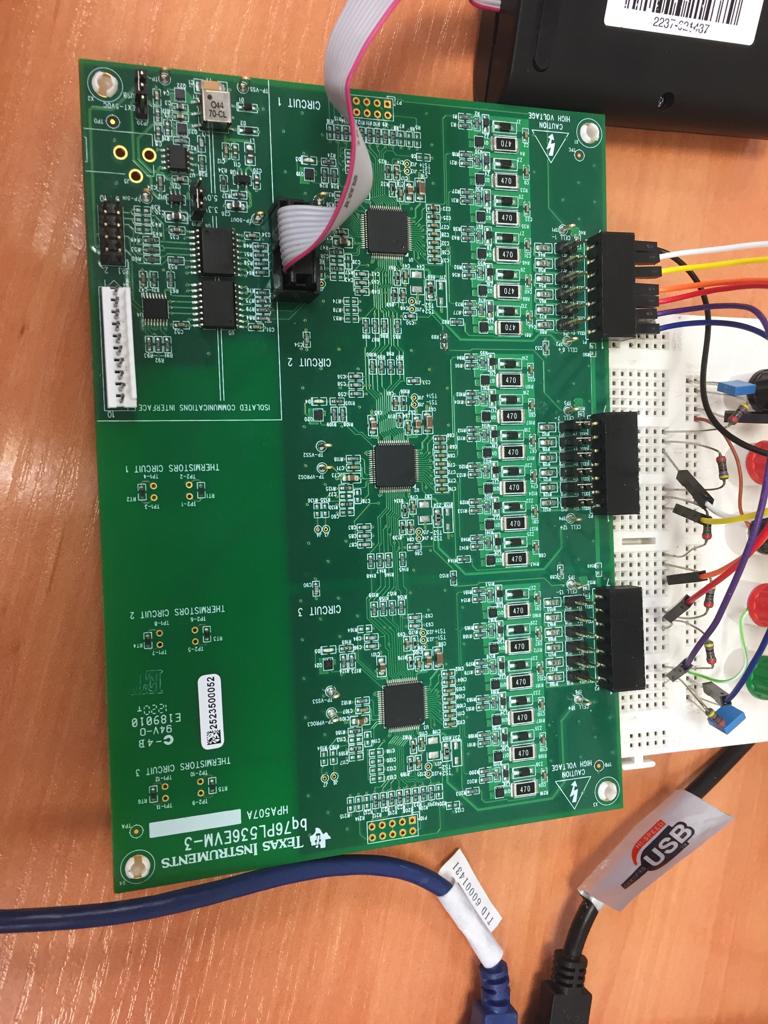
I am using for my "end of degree thesis" this device coneccting it to 6 LiPo battery cells in order to watch every cell voltage in my PC. Unluckily, and though I have installed the drivers which are needed and following step by step your queeck start guide, a warning appears when I try to connect it. This warning says: "there were no devices found".

I have already checked out every connection and made sure the voltage reaches out the integrate circuit, so I have no idea what is going on.

Could anyone provide me some information about what I'm probably doing wrong?

In fact this is the same problem that an user from this page had two years ago, but I do not know how did he solve it. I`m leaving a link here that takes you there:

"https://e2e.ti.com/support/power-management/f/196/t/491308?BQ76PL536EVM-3-isolated-comm-interface-doesn-t-get-5V-and-GUI-cannot-find-devices-"

Thank you!

Nicolás González

  • Hi Nicolás,

    Welcome to the forum! the link that you shared refers to the bq76PL536 device, but your question seems to be related to bq76PL455. Can you please confirm which of these 2 devices you are using?

    Best regards,
    Leslie
  • Hi Leslie,

    Looks like I have become clueless, I am using bq76pl536

    Im sorry for this missunderstanding. Greetings,
    Nicolás
  • Hi Nicolás,


    Have you installed the Aardvark driver?

    Roger
  • Hi Nicolás,

    No problem, thanks for the clarification. Let's start with debugging the hardware to make sure your setup is correct before moving to the software.

    * Can you please confirm if any changes have been done to the EVM?
    * Please share a picture of your setup to see your connections as well as the jumper configuration you have on the board
    * Are you using battery cells or a power supply with a resistor ladder? For initial debugging, I recommend using a power supply
    * After power up, what is the voltage observed on BAT, LDOA, LDOD1, LDOD2, REG50 (5V) pins, and what is the current on BAT?

    Best regards,
    Leslie
  • Hi Roger,

    Of course I did, they were succesfully installed. The problem comes when I try to communicate my module with my computer.

    This EVM module has two USB connection points. One for an isolated connection and the other one without any isolation. I have checked both USB connectors and the same problem comes out.

    Every pin has the required voltage but my suspect is about the SPI communication, maybe some signals are not entering the IC. What advice or recomendation could you give me?

    Thanks a lot and sorry for my English

    Nicolás

  • Hi Leslie,

    I can confirm any changes were done on the EVM.
    As you say I am using a power supply connected to some resistors.
    After power up, the voltage you have asked me are:

    BAT 18V (voltage I am using as supply)

    LDOA almost 3V

    LDO1 and LDO2 have no voltage

    REG50 5V

    Another question I would like to ask is, what is the LED called D3, D4 and D5 for? In the schematic sheet I can see where they are ubicated but I do not know their job.

    I am including a picture of my EVM and its connections.

  • Hi User,

    LDOD1 and LDOD2 have to be 5V when you power on the device.
    Please double check the set-up.


    Please connect Aarvark to the P5. It works better there.

    Roger
  • Hi Nicolás

    LED is optional for real system.
    We added LED to indicate whether IC is ON or not.
    LED will go away in sleep mode.

    Do you see LED on when you connect and wake up the device?

    Are you using real cell or resistor divider?
    Can you show me how you power the 536evm?

    roger
  • Hi Nicolás

    I will close this tread.
    Please let us know if problem is not solved.

    thanks
  • Roger,

    Sorry I didn't answered. Looks like the Evauation Module was already damaged when I started to use it. Thanks for your attention anyway.

    Before you close this tread, can you confim if the software you provide to show the measurements is valid for any single BQ76PL536A-Q1, or is it only used for the EVM?

    Thanks a lot again and sorry for being absent for so long.

    Nicolás


  • Hi Nicolas,

    I am not clear what you are asking?

    Our GUI can measure upto 32 devices and it can be used with your own custom board as well.

    I am not sure whether I answered your question or not but let me know if my answers are not clear.

    thanks

    Roger

  • Roger,

    Let me explain at all:

    After knowing my EVM is dead (it was used before me and it was probably shortcircuited), I have made my own prototype which includes one single BQ76PL536A-Q1

    My question was if I could still use the GUI you provide, so your answer is perfectly clear. One last question, could you recommend me some SPI to USB adapter for this job?

    Thank you again
    Nicolás
  • HI Nicolás,

    You can use Aardvark. You can find the details in the PL536A user's guide.

    Roger