This thread has been locked.

If you have a related question, please click the "Ask a related question" button in the top right corner. The newly created question will be automatically linked to this question.

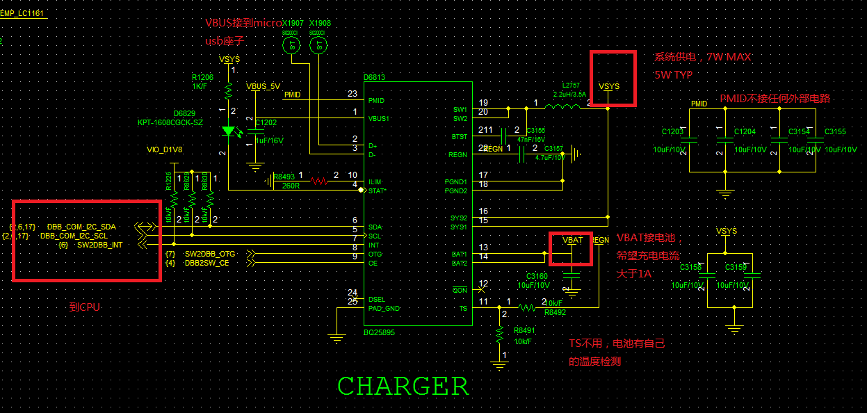
BQ25895: review schmatic

Part Number: BQ25895

Hi team,

1. Would you please help review the schematic below? They want to achieve charge more than 1A, and the system need 2A at work.

2. In addition, how do we use the USB signal here? For communication or charging?

3. Our batteries have a need for seat charger like figure 2. When the device is plugged into the seat charger, the CPU can read the relevant information. At this moment, BQ25895 needs to turn off the charging function. Can BQ25895 realize this function?

  • Hey Jeff,

    I have a few comments on your schematic:
    1) What is the maximum input voltage on VBUS? If it is only 5V USB, I would still recommend increasing the voltage rating on the PMID capacitors to 16V similar to the VBUS capacitor. If the voltage is even higher, I would increase all capacitors even further.

    2) Are the driving signals for /CE and OTG input open-drain or push-pull outputs? If open-drain, are there pull-up resistors for these singals?

    Now to your question about the USB D+/D- lines, these are used for input current limit detection, specifically related to the USB Battery Charging spec v1.2.

    To your question about the seat charger, does the BQ25895 in the device need to disable charge immediately when attached to the seat charger? Or does your CPU need to be able to control the charger to disable charge once the relevant information has been read? Or do you need a hardware implementation to disable charge?


    Regards,
    Joel H