This thread has been locked.

If you have a related question, please click the "Ask a related question" button in the top right corner. The newly created question will be automatically linked to this question.

UCC28051: circuit design question

Part Number: UCC28051

Hello

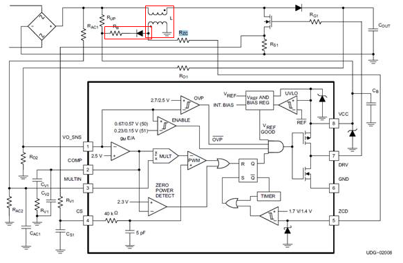
Is the design of the transformer framed in the figure below used for step-down? The design on the Datasheet only calculates a sense but not the number of turns and senses of the transformer's primary and secondary measurements.
The second question is, what is the path for designing the Diode string resistor RB?
Final question is ,how does this IC design the DRV operating frequency?

  • * Is the design of the transformer framed in the figure below used for step-down?

    The inductor is for boost inductor. The coupled winding is for zero crossing sensing and for VCC bias.

    * The design on the Datasheet only calculates a sense but not the number of turns and senses of the transformer's primary and secondary measurements.

    You can refer SLUU138A for the calculation. SLUU138A can be downloaded from the below link.

    www.ti.com/.../getliterature.tsp

    * The second question is, what is the path for designing the Diode string resistor RB?

    RB is a filter resistor for VCC bias.

    * Final question is, how does this IC design the DRV operating frequency?

    SLUU138A equation (1) shows operating frequency f is in relation to the inductance of L (L1 in SLUU138A)