This thread has been locked.

If you have a related question, please click the "Ask a related question" button in the top right corner. The newly created question will be automatically linked to this question.

BQ34Z100EVM: Unsealing and Resetting the Fuel Gauge

Part Number: BQ34Z100EVM
Other Parts Discussed in Thread: EV2400, BQSTUDIO

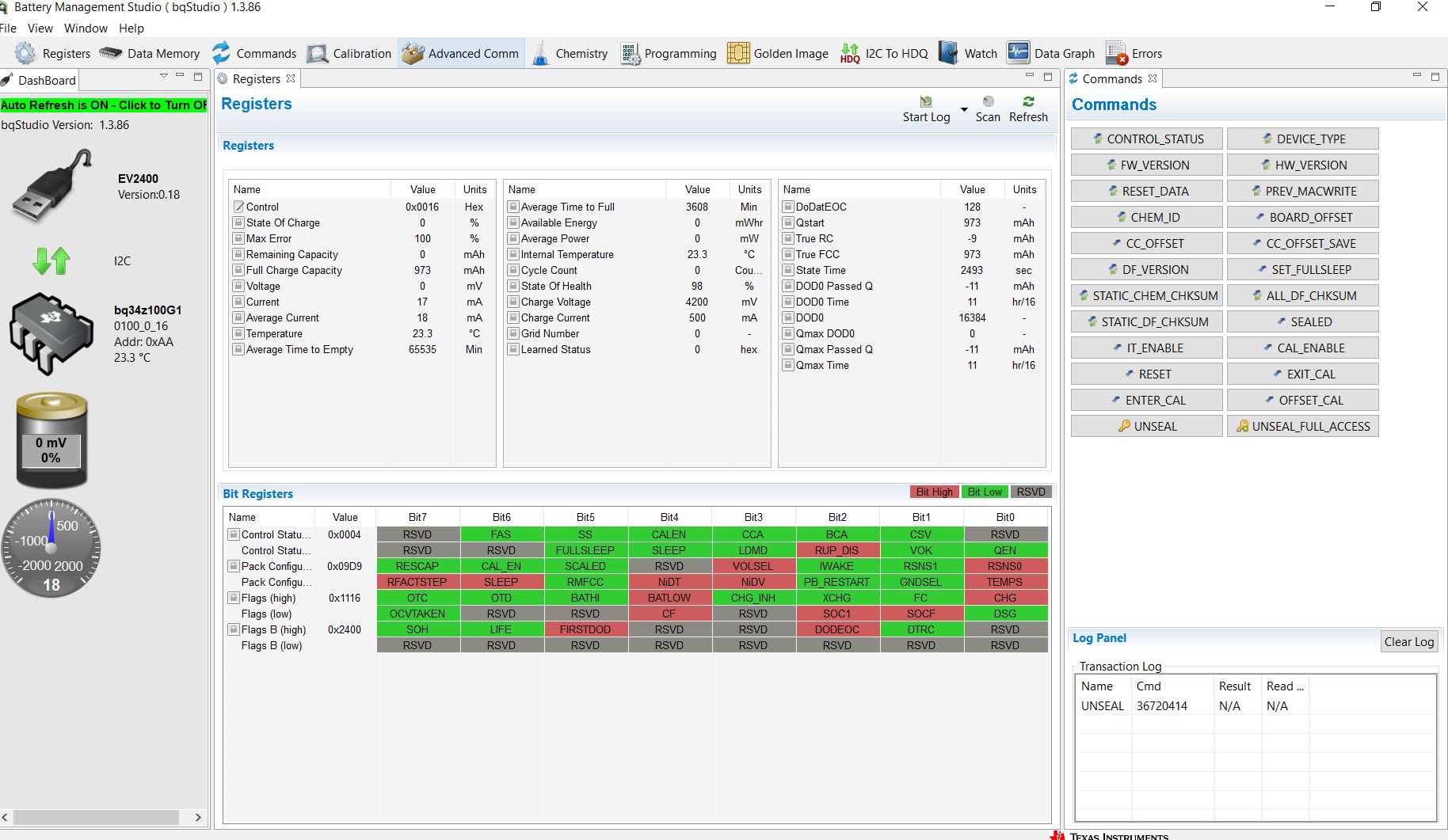
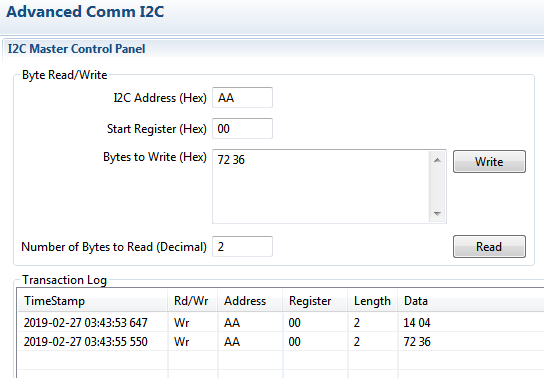
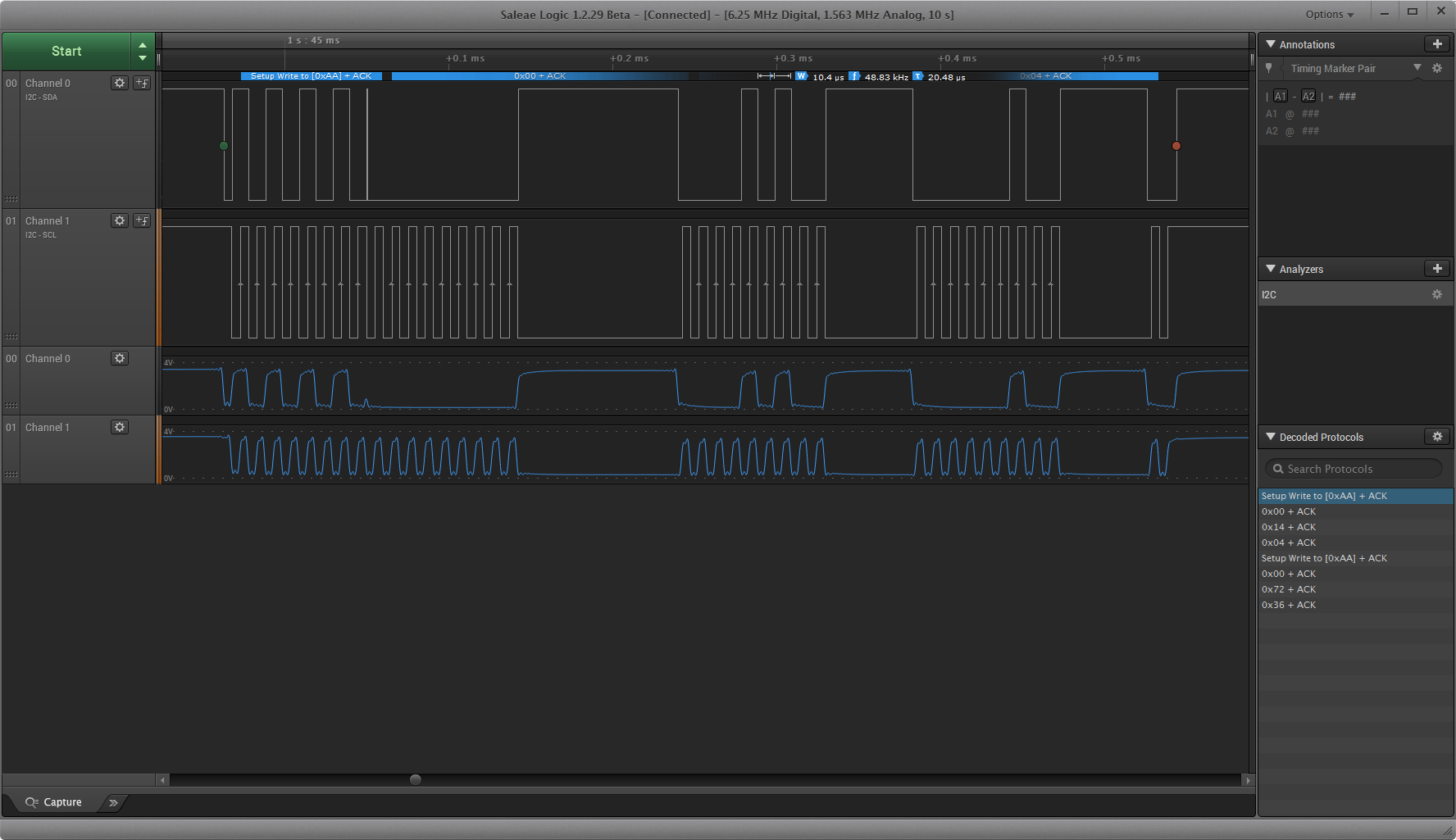
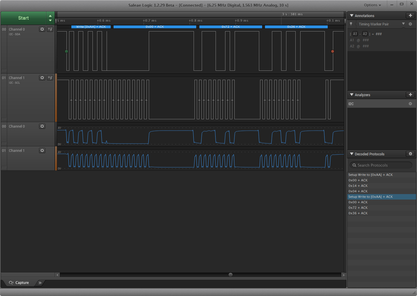
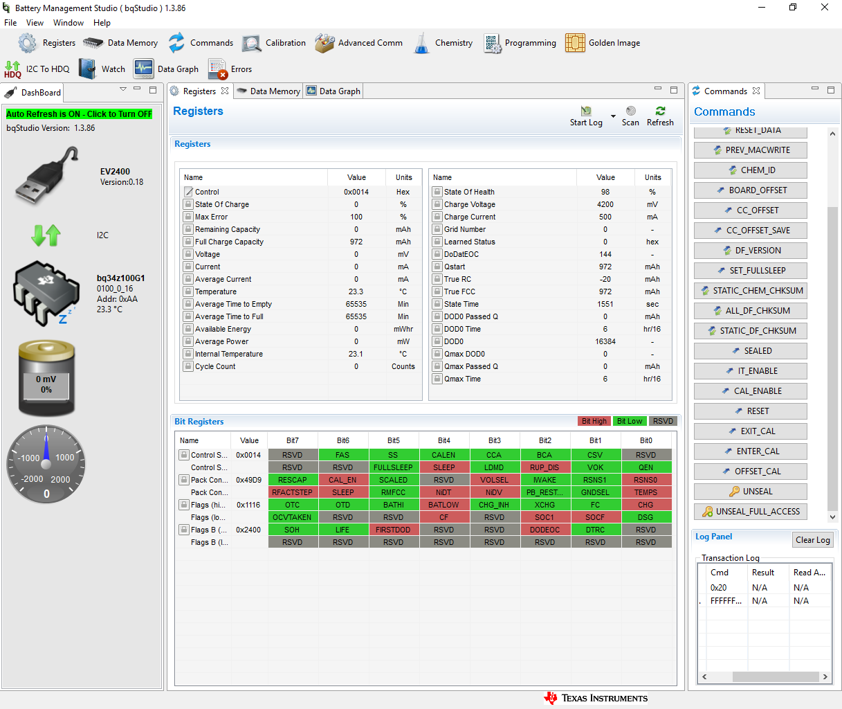
I have a BQ34z100EVM which I want to Reset. If my understanding is correct, I need to unseal the device before resetting it. I used the UNSEAL key using the button in the 'Commands' window on the right side of the BQstudio home screen. Upon doing this, I received the code as '36720414' in the column 'Cmd' in the 'Log Panel' below the 'Commands' window (I've attached a picture of the home screen with the code below). Next, I used the 'Advanced Comm I2C' panel to feed the unseal key. Foll. are the parameters I entered: I2C address: AA; Start Register Address: 00; Bytes to Write: 72 36 14 04. However, the device is not acknowledging this write operation. What are the mistakes in my procedure? Is there another way to unseal the device or reset it directly? Thanks!

  • Hi Ved,

    Turn off auto refresh (green bar at the top of dashboard should now be red)

    In Advanced comm send

    14 04 then 72 36

    To do this quickly, copy 72 36 into the clipboard of your machine, then type in 14 04, click write, highlight 14 04, ctrl-v to paste, click write

    Images below:

    Sincerely,

    Bryan Kahler

  • Thanks a lot Bryan! I was able to unseal the device and Reset it back. Now, I'm trying to calibrate the voltage. I've moved my setup to a new computer that's why I'm facing the following problem:

    So currently: Volsel is low, Both the jumpers on <=5V are inserted, the jumper J1 is inserted and the EXT jumper is inserted.

    Also, I've updated the BQstudio version and the EV2400 firmware. I've connected  a power supply to BAT+ and BAT-. I increased the voltage gradually to 4V. However, the gauge is showing a reading of 0 mV (even after I set BQstudio in scan mode).

    Now, while calibrating voltage (I turned the scan mode off), I ticked 'Calibrate Voltage', entered value of applied voltage (measured via DMM) in the box and clicked on 'Calibrate'. However, it gives me an error and a cross appears besides Calibrate. Also, the gauge voltage is still 0mV on the calibration screen.

    Where am I going wrong? Thanks a lot!

  • Please check if you are in full access mode.
  • Thanks Batt!

    I was able to get full access to the device, after which I calibrated the CC offset and Board offset. No error occurred in this process. Next, I tried calibrating the voltage (4006 mV, was applied by the power supply). However, its giving me an error. Also, the gauge is reading the voltage as 0 mV. 

  • Have you set the jumpers on your evm correctly?
  • The jumper settings are: Both the jumpers on <=5V are inserted, the jumper J1 is inserted and the EXT jumper is inserted.

    I'll detail the entire background before this problem occurred:

    1: I was reading a 1500 mA current & ~3.7 V with my gauge, and the reading was off by 200 mA and 0.2 V, respectively.

    2: To correct this, I was advised to set VOLSEL low, reset the gauge and calibrate it again in this thread.

    3: I turned VOLSEL low via BQStudio. Upon doing this, the BATLOW also went low as the battery connected had a terminal voltage of 3.7 V.

    4: After this, I unsealed the device and reset it.

    5: Now, I'm getting an error in calibrating the voltage as mentioned above.

  • Hi Ved,

    What is your value for voltage divider? If jumpers are set to <= 5 V, please ensure that volsel = 0 and that voltage divider = 5000 mV.

    If you are getting errors in setting any value in data flash, this may be because FLASH UPDATE OK VOLTAGE is too high and/or series > 1.

    If unable to write to data flash, please reprogram the gauge with the default SREC and set FLASH UPDATE OK VOLTAGE = 0 (please do not go below 3 V on regin).

    Sincerely,
    Bryan Kahler

  • Hello Bryan!

    The jumpers are set to <=5 V; VOLSEL=0. The voltage divider was set to 5005 mV, hence I reset it to 5000 mV. However, still the gauge voltage reads 0 mV (even after I refreshed the REGISTERS window) whereas the power supply I've connected is set to 4V.

    The FLASH UPDATE OK VOLTAGE is 2800 mV and NUMBER OF SERIES CELLS is 1.

    I didn't reprogram the IC, but currently my REGIN voltage is 4.03 V (measured on the TP6 pin).

    I've attached a picture of the REGISTERS window beneath:

    P.S.: When I obtain Full access to the device, there appears a 'Zzz' sign next to the IC in the DASHBOARD. Is this okay, or does it mean that the IC is inactive or something? 

  • Hi Ved,

    For this device, the Zzz icon indicates that the device is unsealed and unsealed full access.

    If either of the lock icons were in front of the gauge, commands may not work until unsealed or unsealed full access.

    Please try power cycling the gauge to see if this fixes the issue.

    After power cycling, check to see what value is set for voltage divider. If the issues persist, please program the gauge with the SREC found on the website, here: www.ti.com/.../sluubv2

    Then, follow the bringup steps in the quick start guide, found here (it appears they have all been followed): www.ti.com/.../sluc580

    If the issue still persists, measure the voltage on the BAT pin and let me know the results.

    Sincerely,
    Bryan Kahler
  • Hello Bryan!

    I power cycled the device, but the voltage divider value stayed 5000 and it was still unable to read the voltage. So I programmed the gauge with the .srec file you had recommended and the working of the gauge has gone back to normal. It is able to read the voltages I'm applying to it. Thanks a lot!

    But there's one issue: Before the gauge had started malfunctioning, I was trying to read voltages below 4.5 V and I was having some problems with voltage and current reading (the value was off by 0.2 V and 200 mA respectively) even after calibrating it properly. So you had recommended in this thread that I turn the VOLSEL bit to 0 and then calibrate the device. I turned VOLSEL low by clicking on the 'VOLSEL' bit in the 'Pack Configuration' Register window in the 'Data memory' tab. Upon clicking, the VOLSEL block went red, and that was when the issue with the device not reading the voltage at all started.

    So, what's the correct way to turn VOLSEL low, so as to not affect the normal operation of the device?

    Also, the datasheet specifies the bit name as 'VOLTSEL', whereas the BQstudio interface displays it as 'VOLSEL' (the T is missing). Is there some other bit I need to turn low? Thanks a lot for your help, Bryan!

  • Hi Ved,

    Volsel and voltsel are the same bit (different spelling between the software and datasheet). Volsel should be set to 0 by default with a fresh SREC (Downloaded from the website). Using the default color scheme of bqStudio, when the block is green, the value is 0. When red, the value is 1.

    If no external divider was present when this occurred, 4.5 V may have been sent into the BAT pin with only 1 V expected by the ADC.

    Please ensure the jumpers for the gauge on J5 are populated for > 5 V mode and that one of the 16 V, 32 V or 48 V jumpers of J2 are populated before setting volsel = 1.

    Sincerely,
    Bryan Kahler
  • Thanks a lot, Bryan! I'll calibrate the gauge again and reach out if there's any other issue.