This thread has been locked.

If you have a related question, please click the "Ask a related question" button in the top right corner. The newly created question will be automatically linked to this question.

TPS54622: TPS54622 dynamic management

Part Number: TPS54622

Hi,

I wanted to implement dynamic management on TPS54622 basing on TI doc SLVA861–December 2016"How to Dynamically Adjust Power Module Output Voltage"

The schematics is attached . Input voltage is 15V. Output voltage is 12V which managSCHEMATICS _ 03 POWER.pdfd within range +-10%.As DAC I am using MCP4725. In general management is working. However I have problem with current transient.When I running transient from 1Amp -> 0Amp during tens microsecond the TPS54622 is burn out: input and output of the chip are short connected to GND pins. Could you hint what can be a problem?

Thank you

Stas SCHEMATICS _ 03 POWER.pdf

  • Hi Stas,

    The first thing I noticed is the EN pin is being pulled up to the 15V input. The EN pin is rated for only 6 V on this part. Could you try populating C10 with a resistor instead so that there is a voltage divider? A 4.7kΩ should divide the 15V down to ~5V.

    If that is not the problem, the IC shorting to ground suggests some other type of over voltage stress may be occurring. Can you perform this load transient test again while probing the PVIN pin voltage and PH pin voltage with an oscilloscope? Getting some waveforms at the time the damage occurs should help debug this.

    Best Regards,
    Anthony

  • Hi Stas,

    I'm going to mark this issue as resolved for now. If you still need help, please post again to re-open this thread.

    Thanks,
    Anthony
  • Hi,

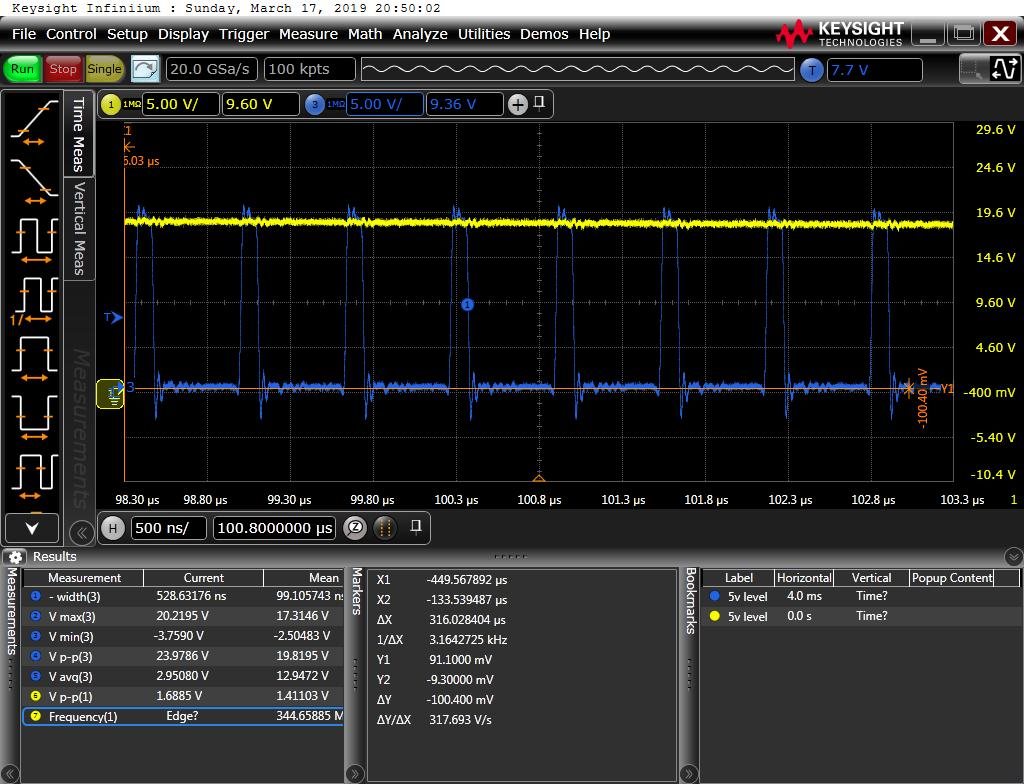
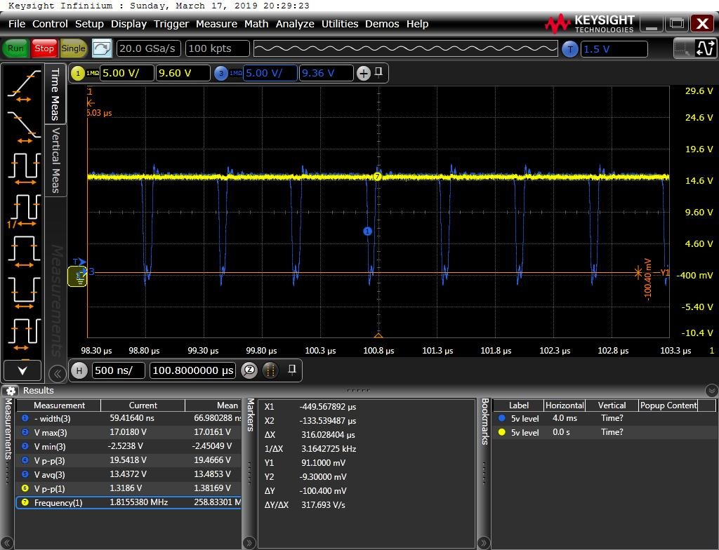
    I followed to yours recommendation and divide Ven. It's improve situation from my point of view: before PS was damage even during switch on. Now it pass switch on, I load it with 0.5Amp and 0.9 amp without problem. It was still working. But during transient 0 to 1A the PS damaged once more in the same way as before. I tried to capture picture in PH but it difficult to capture it in the same time when chip damage. NeverthelessI am sending you two files . One shows regular diagram of PH. and second one  - damage situation(although it difficult to understand when it happen but it seen something went bad- duty cycle is wrong. Do you have any additional idea?What can be reason for such damage?(overvoltrage? negative voltage? something else? Do you see any problem to work with such duty cycle?

    Thank you in advance

    Berlin Stas

  • Hi Berlin,

    Can you help verify if it is the second image or the first image showing the part operating normally? The second image looks like normal operation because this is where the duty cycle matches what I expect. For 15 V input to 12 V output the duty cycle should be ~80%.

    I've taken another look at the schematic and do not see any issue with the component values. The only comment I have is on the fsw. I do not think the high fsw is a cause of the problem but I would consider using a lower fsw because of the high duty cycle application. 800kHz should work well with the current component values.

    Also, have you verified on a board that is not working normally that replacing only the TPS54622 fixes the problem? I had assumed this was done but I want to make sure.

    Best Regards,
    Anthony
  • Hi Berlin,

    Just checking in to see if you have been able to resolve this issue. Please let me know if you need any clarification on the questions in my last post.

    Thanks,
    Anthony
  • Hi,

    Yes, this is resolved issue

    Thank you

    Stas