This thread has been locked.

If you have a related question, please click the "Ask a related question" button in the top right corner. The newly created question will be automatically linked to this question.

UCC29950: MOSFET of PFC stage and UCC29950 blown up.

Part Number: UCC29950

Hi, 

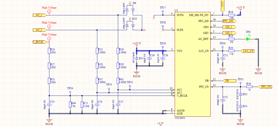
I have a problem using UCC29950. I'm building a 400W power supply. During startup the UCC29950 is powered by an external Power supply set to 15V and connected between GND an VCC pin of UCC29950. 

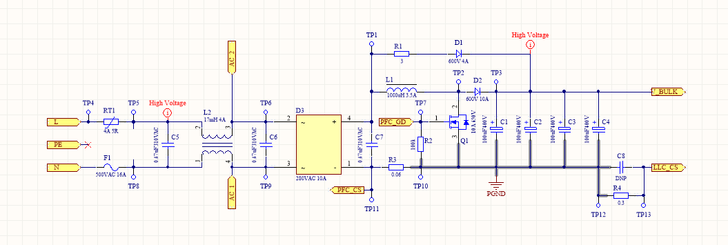
The Value for the PFC current sense resistor is 0.06Ohm the inductance of the PFC Inductor is 400uH. When I increase the input AC voltage and the MDS_ON pin gows low, the PFC MOSFET is blown up and also the UCC25590 is killed. I'm not using a gate driver for the PFC MOSFET.

Please help... 

  • Hi Christian,

    I have contacted one of my colleagues to answer this post.

    Regards,
    Teng
  • Hello Christian

    Your schematic looks ok except for a couple of relatively small points:
    You are using an external bias supply which means that the controller should be configured in Aux Bias mode. Inthis case, SUFS should be connected to VCC and SUFG should be left open circuit.
    The UCC29950 will operate in Aux Bias mode when the MD/SEL pin is held low for at least 10ms after VCC is applied. You can hold MD_SEL low indefinitely of course and this will prevent the power stage operating.

    The UCC29950 is probably being damaged when the power MOSFET fails - so the first thing to do is to try to understand what is happening.

    If you can repair the PSU then I'd try the following.

    I think that the first thing to do is to look at the PFC stage switching waveforms.
    Remove the line voltage and VCC from the UCC29950, and disconnect the PFC_GD pin from the gate of the power MOSFET.
    Remove the gate drives to the MOSFETs in the LLC stage and short their Gates to their sources.
    Put a 'scope probe on the Gate of the PFC MOSFET and on its Drain. Use a 0/10V square wave generator, set to 100kHz and use this to turn the power MOSFET on and off - make sure that the generator output impedance is not set to 50 Ohms.
    Then set L and N to a low DC voltage - maybe about 10V. Check that the drain and gate of the MOSFET are working as expected. Vout should be about 2 times VIN because the square wave has a fixed 50% duty cycle. Make sure there are no excessive spikes on the drain or gate.
    Then slowly increase Vin until Vout reaches 400V, checking all the time that there are no excessive voltage spikes.
    Finally, use a DC load to load the PFC output - a few Watts up to your full power.
    If the power stage is ok then it would be time to use the UCC29950 to control it.

    Leave the PFC stage as it was during the earlier tests. Remove all power from the system. Short MD_SEL to GND . Then apply VCC to the UCC29950 controller. Then slowly increase the AC line voltage to 120V. The power stage won't be active of course but this will allow you to check that the voltage levels at the pins of the UCC29950 are as expected. I would also check that the PFC stage bulk capacitor has charged to peak of line voltage - about 170V or so.

    Finally, remove all power from the system, reconnect the PFC_GD pin to the gate of the power MOSFET. Remove the short between MD_SEL and GND and then use a small signal MOSFET or the signal generator to keep MD_SEL low. Then apply VCC to the UCC29950 controller, apply 120Vac to the line input and then release the MD_SEL pin for a short period - maybe about 50ms or so. Use the 'scope to capture some of the switching waveofrms, Vg and Vds during the burst of switching.

    The idea is to try to figure out why the MOSFET and IC are failing - the tests above should allow you to find and fix the problem.
    Please feel free to post any waveforms here and to ask if you have any questions.

    Regards
    Colin
  • Hello Christian

    I'm closing this thread. Please feel free to open a new one at any time if you have a question.

    Regards
    Colin