This thread has been locked.

If you have a related question, please click the "Ask a related question" button in the top right corner. The newly created question will be automatically linked to this question.

BQ25703A: Not charging, current resets to zero

Part Number: BQ25703A

Hi,

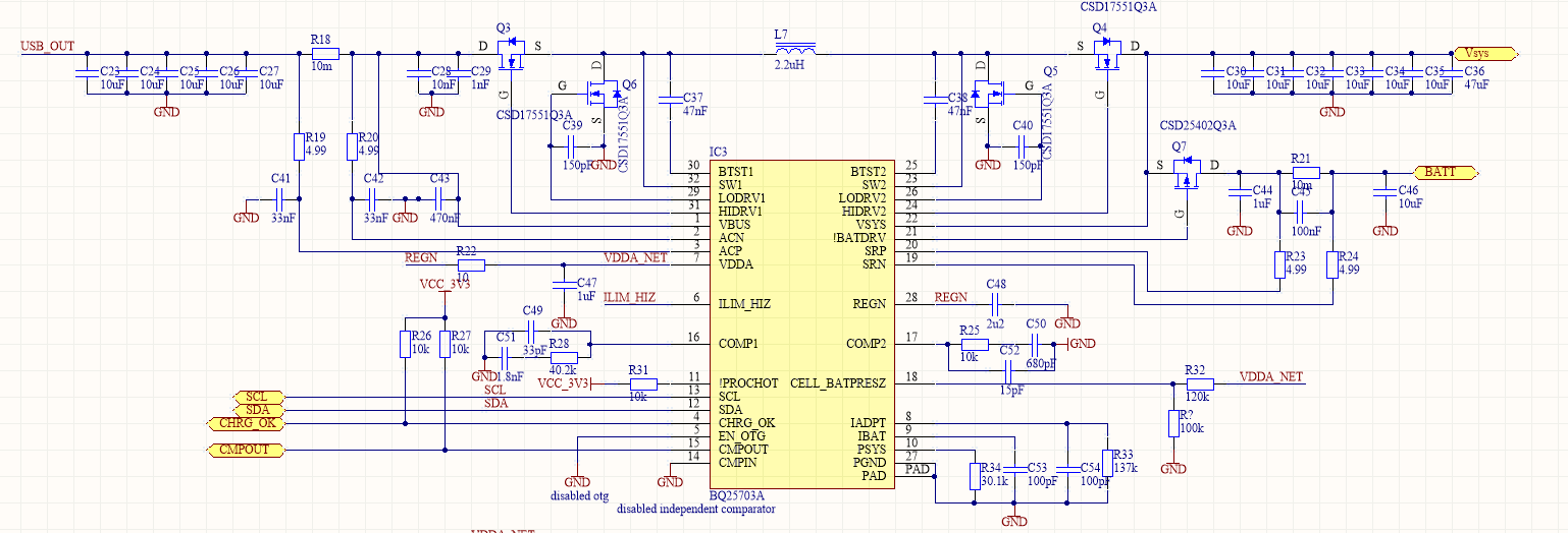
I have problem with charging 2S Li-Ion pack with BQ25703A. Let me describe my circuit. It is based on EVM module. No significant changes just simplified a bit the input protection.

Settings of the BQ25703A.

First I write 0x40 to register 0x35 to reset all of the registers.

Second is go out of low-power mode – 0x2 to register 0x1.

Write default values– 0x0E to register 0x00.

Enable Ibat and Psys - 0x92 to register 0x31.

Disable comparator and enable auto-wakeup – 0x01 to register 0x30.

Enable ADC in continuous mode - 0xE0 to register 0x3B.

Enable all of the ADC measurements – 0xFF to register 0x3A.

Min system voltage 6.144V – 0x18 to register 0x0D.

3.2A current limit – 0x40 to register 0x0F.

3.2A current limit in DPM – 0x40 to register 0x25.

3.2V min input voltage – 0x00 to register 0x0B.

512mA charge current – 0x02 to register 0x03.


I start the device with battery supply then start my bench supply at 5V and feed it into charger input. Charge current is resend about once per second. When I read back the 0x03 register I receive only zeros. When power supply is ON status register 0x21 reads back 0xA0 which corresponds to detected AC adapter and 5th byte set (which should be reserved and stay as zero). Fault register (0x20) returns 0. Register 0x29 and 0x28 always returns 0. I think one of them should show current consumption of my device. Is there anything that I should check? Are there any settings wrong?

Thank you,

Blazej


  • Hello,

    Can you also provide your test conditions, such as input voltage, input source power capability, battery voltage, load current, etc?

    Do you also have the register readouts of the other registers you did not report, such as charge voltage?


    Regards,
    Joel H
  • Hi,
    Thank you for the response. Here is all of the info that you asked for.
    Input voltage of the supply 5v, current limit of the PSU is 3A (connected device never exceeds 300mA of input current), battery voltage 6.75V (2S Li-Ion), my system draws 200 mA current from battery.
    Only one additional change between previous post is change reg 0x32 value to 0x37 (changed source of ILIM to configured through I2C) - no improvement.
    Here are all of the register readouts done after the setup of the device.

    reg_00	 	0xe  	
    reg_01	 	0x2  	
    reg_02	 	0x0  	
    reg_03	 	0x0  	
    reg_04	 	0xd0  	
    reg_05	 	0x20  	
    reg_30	 	0x0  	
    reg_31	 	0x92  	
    reg_32	 	0x37  	
    reg_33	 	0x2  	
    reg_34	 	0x0  	
    reg_35	 	0x0  	
    reg_36	 	0x54  	
    reg_37	 	0x4a  	
    reg_38	 	0x20  	
    reg_39	 	0x81  	
    reg_3A	 	0xff  	
    reg_3B	 	0xa0  	
    reg_20	 	0x0  	
    reg_21	 	0xa0  	
    reg_22	 	0x0  	
    reg_23	 	0x0  	
    reg_24	 	0x0  	
    reg_25	 	0x40  	
    reg_26	 	0x1  	
    reg_27	 	0x19  	
    reg_28	 	0x0  	
    reg_29	 	0x0  	
    reg_2A	 	0x0  	
    reg_2B	 	0x0  	
    reg_2C	 	0x3c  	
    reg_2D	 	0x40  	
    reg_06	 	0x0  	
    reg_07	 	0x0  	
    reg_08	 	0x0  	
    reg_09	 	0x0  	
    reg_0A	 	0x0  	
    reg_0B	 	0x0  	
    reg_0C	 	0x0  	
    reg_0D	 	0x18  	
    reg_0E	 	0x0  	
    reg_0F	 	0x40  	
    reg_2E	 	0x40  	
    reg_2F	 	0x78  

    Blazej

  • Hey Blazej,

    Can you measure the voltage on the ILIM_HIZ pin?

    Is it just floating or is it connected to a resistor divider?


    Regards,
    Joel H
  • Hi

    ILIM_HIZ stays at 4.5V. It is connected via resistor divider. Voltage stays the same on just battery supply and battery + power supply.

    Blazej

  • Hi,

    Do you have any ideas what is wrong with my circuit?

    Blazej

  • Hey Blazej,

    So the ILIM_HIZ at 4.5V should only disable the external IINDPM feature when its above 4V. You can try changing this resistor divider to something below 4V to see if it has any impact but I doubt it.

    The only thing I can think of when looking back at your schematic is checking the CELL_BATPRESZ voltage. From what I can see, there is a 100-kOhm resistor pulled to ground but the component does not have a designator assigned, just "R?" What is this component placed?

    This charger uses CELL_BATPRESZ to determine if a battery is present and will stop charging otherwise.


    Regards,
    Joel H
  • Hi,

    CELL_BATPRESZ stays at 2.7v no major difference between PSU and just battery supply.

    Changed ILIM_HIZ to 3.5v. No changes, no charging, no faults visible in registers.

    Do you have any more ideas? I can provide more measurements and osciloscope measurements in any part of the circuit for you to debug.

    Blazej

  • Hey Blazej,

    Let's start taking some waveforms them.

    Can you capture the following nodes?
    VBUS, VREGN VSYS, and VSRN after an adapter plug-in/power supply turn-on.

    You will likely want the time scale to be in hundreds of microseconds. I just want to check that the converter is switching and that the system voltage is regulated as it should be.


    Regards,
    Joel H

  • Hello,

    Thank you for the response. Here are requested measurements. In the bottom i prepared Vpp, Vavg and Vmin. There is a bit of a ripple but shouldn't be a problem in my opinion. What should I check next?

    Vregen:

    Vbus:

    Vsys:

    Vsrn:

    Best Regards,

    Blazej

  • Hey Blazej,

    I think we are going to need to see multiple channels on a single scope capture, and we want to trigger on an initiating event.

    So lets take the following:
    CH.1 /BATDRV
    CH.2 VSYS
    CH.3 VBAT
    CH.4 VBUS

    And we want to trigger on the falling edge of the /BATDRV signal. Now, it should trigger or attempt to pull low when you write to the charge current register.

    And just to confirm, what does the data packet look like on your continuously transmitted charge current setting.
    I also looked back at your original comment about reading the status register, but did you also continuously monitor the fault registers when you are continuously programming the charge current (reading the fault registers after you program the current).


    Regards,
    Joel H
  • Hi Joel,

    I figured it out. After current write !BATTDRV never went low. I tried one last thing in firmware. In previous code I have just written 0x3 register with value corresponding to 0.5A. Today I tried to write whole register pair 0x2 and 0x3 with one write. This worked fine and batteries are charging. Thank you so much for your help. 

    Blazej