This thread has been locked.

If you have a related question, please click the "Ask a related question" button in the top right corner. The newly created question will be automatically linked to this question.

Are there amplitude adjustable chip when feeding a PWM signal?

Hi, I have an EXP-MSP430G2 launchpad (operating voltage 3.3V) and an Arduino Uno board  (operating voltage 5V).

I'm just testing PWM examples with the boards.

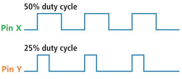
Each board uses two pins which creates PWM like the above picture. The frequency of the PWM signals, generated from the boards, will range to 5 ~ 1,000 Hz.

I want to change the amplitude of the 2 PWM signals to a higher level, a range 10~40V.

But instead of using something like a motor driver/Op Amp, which has a fixed amplitude/feedback resistor(manually changing the potentiometer with the hand is not I want), I want to control the amplified voltage using either my launchpad or the Arduino.

Are there any power ICs from TI that can adjust the amplitude of the output signals? It would be appreciated if the IC can be installed on a 2.54mm pitch breadboard.

I don't want to use a potentiometer to control the output of a boost converter. Rather, I want to use serial communications (SPI, UART, etc) to adjust the output of the PWM signals, please.

Thanks for your help.

  • David,
    Your request to have an adjustable amplitude for a PWM signal without adjusting the power supply defeats the purpose of using a PWM signal. We use PWM for Class D amplifiers for maximum efficiency of the output stage of the amplifier. We either turn off the output transistors or turn it on in hard saturation. By varying the amplitude without changing the power supply, does not allow for turning off the output transistors. They will be operating in linear mode and have higher power dissipation and thus lower efficiency.
  • Gregg Scott said:
    Your request to have an adjustable amplitude for a PWM signal without adjusting the power supply defeats the purpose of using a PWM signal.

    Hello, Gregg. You mean, I have to fix the voltage supply (40V for instance) and adjust the duty cycle?

    I wanted to use the same duty cycle but change the amplitude. Although I can do this by adding an Op Amp and a potentiometer,

    an analog potentiometer is not I wanted because I have to control it with myself.

    I also tried digital potentiometer, but it provided an unstable output.

    So that's why I was looking for an alternative solution using TI's components.

  • David,
    PWM stand for pulse width modulation. The pulse width or duty cycle is modulated. You are correct, the power supply is fixed and the duty cycle is adjusted. Then an LC filter is used to filter the PWM frequency out of the signal and the modulated signal is left. The PWM frequency must be much higher than the modulated signal.
  • Thanks, Gregg.

    Before closing this can I ask one more thing;

    Are there any Op Amp devices that can digitally change the feedback gain from TI?

    For instance,

    - an Op Amp that uses I2C(TWI)/SPI in order to change the output gain

    - a digital potentiometer, which uses I2C(TWI)/SPI, that can be used to change the gain of the Op Amp's feedback

  • Sorry, for not getting back to you. TI has many digital potentiometers. Go to ti.com and search "digital potentiometer".