This thread has been locked.

If you have a related question, please click the "Ask a related question" button in the top right corner. The newly created question will be automatically linked to this question.

BQ25601D: Simulate and set input current limit on D+ D- pins on BQ25601D

Part Number: BQ25601D

Dear *

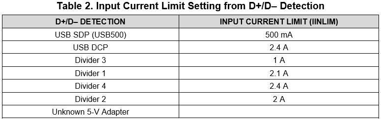
if we connect pin D-(3) and D+(2) together -> short on the BQ25601D -> then the input current limit IINDPM will be set to max 3.25A ?

what will happen if the D-(3) and D+(2) are left floating? -> is then the IINDPM default value of 2.4A?

Can we simulate a resistor divider on D+ D- to get the IINDPM set to 1.5A?

Is there a correlation between resistor divider on D+, D- and the Input current limit register values ?

Best Regards,

David.

  • Hi David,

    If D+ and D- are shorted together, then the BQ25601D will automatically identify a DCP and set the input current limit to 2.4 A.

    As for your other questions, the purpose of the resistor dividers is to set the appropriate voltages on the D+ and D- pins so that the BQ25601D can recognize what kind of adapter is plugged in. If the voltages on D+ and D- are not recognized as one of the adapters in the table below, then the BQ25601D will treat it as an unknown adapter and set the input current limit to 500 mA.

    Therefore, there isn't a direct correlation between the resistor dividers on D+/D- and the input current limit settings, so resistor dividers should not be used to modify your input current limit. Anything not defined in the table above will be treated as an unknown adapter, and the input current limit will be set to 500 mA. Instead, the host should write to register REG00 bits[4:0] and set the input current limit to your desired value.

    Best regards,

    Angelo