This thread has been locked.

If you have a related question, please click the "Ask a related question" button in the top right corner. The newly created question will be automatically linked to this question.

LM334: Question about Vin

Part Number: LM334
Other Parts Discussed in Thread: LM4132

Hi, could someone please specify what Vin should be? I am trying to obtain a 1mA current source (temperature compensated). However changing Vin is also changing the output current hence I am not sure.

Moreover Vin is shown at V+ meaning that it is the supply voltage and where should the ground be connected? To V- or to the other end of the load source.

I am also open to better current source ideas/modules.

Thank you

  • Hi Luke,

    How much precision do you need on the 1mA current source?
    How much is your Vin changing?
    Do you have enough overhead on Vin to handle a 1mA current with your load?

    The set current of the LM334 will vary slightly with the input voltage. This is characterized on the EC table as "Average change in Set Current with Input Voltage." If the device deviates more than this, it might be a setup issue.

    V+ is Vin for typical applications where Vin is positive and the LM334 is on the high side. GND is connected to the negative of your load.

    -Marcoo
  • I aim to use it for an ohm meter application hence ideally it should not vary too much. My Vin from the power supply is stable however I was not sure value to set it to since the current varied. However I will re check and re confirm this since I was connecting V- to GND which is not correct. What should I set Vin to?

    Furthermore in a similar thread to this, someone mentioned using the LM4132 as a current source. Would I be better off using that or something similar?

    Thanks
  • The loads which I aim to measure and identify are quite far apart hence a small change in the current source should not have such a drastic effect in identifying the load.
  • Upon further testing I am noticing current changes with changes in the load, could be because the load is reactive perhaps?
  • Hi Luke,

    What is the V+ voltage you are using?
    What is the resistance of the load?
    Do you have a schematic?

    -Marcoo
  • Hi Marcoo,

    I am using a 9V supply but I am not obtaining 1mA as supposed (that being said anything up to 10mA is fine as long as the current is stable).

    The load is an 8ohm speaker however the current changes when I use 10ohm carbon film resistor.

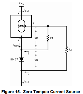
    Attached please find a schematic as used from the datasheet. R1 = 130ohm and R2 = 1.3kohm

  • Hi Luke,

    Sorry for the delay. I'll look into this for you.
  • No worries Marshall! Thanks :)

  • Hi Luke,

    Does the constant current source continue to provide a constant current when the speaker (load) is applied? Does the current source collapse?
    How are you measuring the current? What is the precision of the meter?
    If you want to test functionality of your ohm meter design, I suggest sweeping a purely resisitive load on the output of the current source. What I think might be going on is you are applying a very heavy load and you are causing one of the circuit overheads to not be fulfilled.

    Please get back to me with the answers to the questions and we can work on analyzing the circuit together if you are still having issues.
  • Hi Marshall,

    The current is sustained across the load and I am measuring the voltage drop across the load since it is more significant using a UNI-T multimeter.

    The load applied is usually around 8ohms. Should I expect to current output to change with a change in the supply? I cannot define that relationship yet since in the application note it is not mentioned.

    Also should I expect the current output to change since the load is reactive?

    In another thread someone mentioned to use an LM4132 which has a current output application - since the LM334 is an old component now. Would you suggest that?

    Thanks a lot for your help, much appreciated!

  • 1. No, the current shouldn't change with load, assuming everything is being biased up correctly (I will get into what I mean next). Here are two exceptions to that, I can think of:
    a. You apply a load and the voltage drop in combination with the forward voltage on the diode (ie: 0.65V), results in the forward voltage of the LM334 being violated. In the datasheet, there is a specification called "forward voltage" that range is from 1V to 40V.
    b. You are not sourcing enough of current to "turn on" the diode. Most small signal diodes require several millamps of current to forward bias them. This bias current (in the circuit you designed) comes from the current source and the current flowing through R1.
    2. Steady state, the current being sourced should be all dumped into the resistive component of the speaker. The measured voltage drop would be the current sourced (1mA) times the resistive componet of the speaker.
    3. Both are excellent devices. I think for your application, either device would work.
  • Hi Marshall,

    Again thank you for getting back to me and providing me with valuable answers.
    I'll look into points (a) and (b) in particular however I used the resistor values recommended by the application note - please refer to pg9 of the data sheet.

    Perhaps the main issue which I found was the change in output current with Vin; again I was using Fig 15 of the data sheet as a guide however Vin is not specified. Changing Vin from 3V to 9V resulted in a vary different output current. The data sheet example mentions the resistor values for 1mA output current but not Vin that should be applied. Again, I had to vary Vin until I obtained a 1mA current output - is this usual ?

    Thanks and regards,
    Luke
  • Let me know how this goes, Luke!!
  • Hi Marshall, would you mind confirming whether a change in Vin should change the output current? As explained in my previous reply I followed the example of the data sheet but did not know what to set Vin to get a 1mA current output.
  • Please see the figure below. You are asking should changing V+, affect the output current for a fixed ISET (fixed RSET)?

    So what I would expect is as you ramp up the supply voltage (V+) from 0 to 1V, the current will increase until it becomes saturated. 

  • Hi Marshall my R1 = 130 ohm and R2 = 1300 ohm making Rset = 1430ohm. This is weird since my output current varies for V+ ranging from 1V and above.
  • Maybe you could monitor the voltage on the V- terminal of the device. V- will definitely not be non-zero. The horizontal axis of the figure above is the difference between V+ and V-.

    It may be a good exercise to just design up the typical circuit in figure 13 of the datasheet and trace out these curves, to get a deeper understanding for device operation. You could also simulate in SPICE if you think that may be more efficient.
  • Hey Marshall thanks for pointing out that it's the difference between V+ and V- (my bad for not reading the axis properly). Also comparing the curves and using SPICE are also very good ideas.

    Thanks a lot for the help Marshall, I appreciate it a lot. I'm gonna mark this as resolved for now; I should be able to continue working on the circuit soon - but this information should be enough.

    Kind regards

    Luke

  • Dear Marshall,

    or whomever might have encountered a similar problem.

    I feel quite dumb to post this however I have found my problem; which is the pinout - by mistake I did not note the (bottom view) in brackets in the data sheet so I had the pinout wrong all along.

    Device works fine now :)

    Kind regards,

    Luke

  • Let me know how the final product turns out!
  • Cheers Marshall! The type of wires used to measure the load are having an effect on the readings but I guess that is to be expected unless the wire's resistance is measured and subtracted as an offset I think...