This thread has been locked.

If you have a related question, please click the "Ask a related question" button in the top right corner. The newly created question will be automatically linked to this question.

UCC29910A: 3 Phase 400Vac (rectified DC Bus 540VDC) @5000W PFC Buck possible

Part Number: UCC29910A
Other Parts Discussed in Thread: UCC29910, STRIKE, , UCC28070

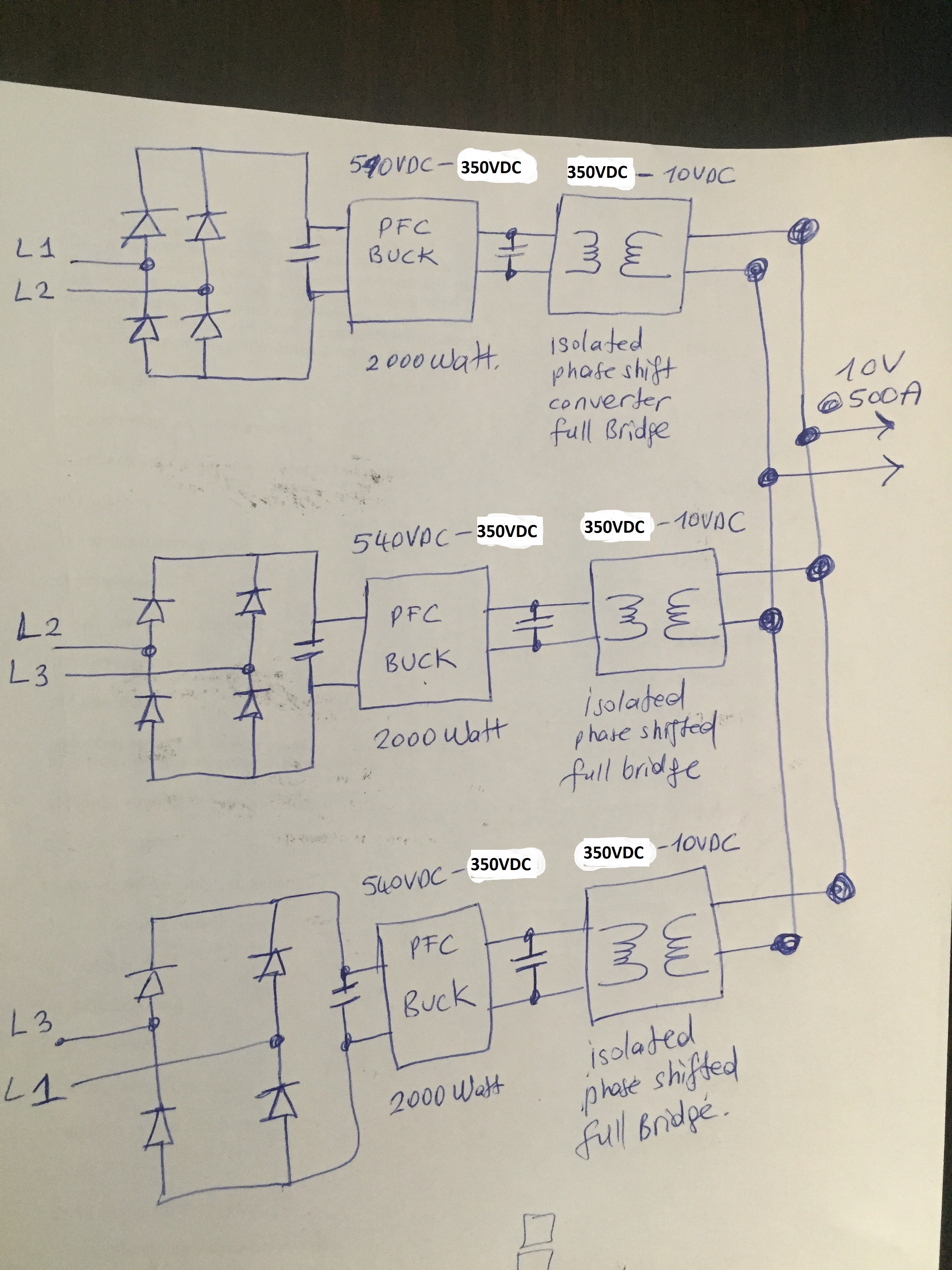
I am trying to build a power factor correction converter for the following setup:

Line Voltage: 3 phase 400Vac (rectified Dc bus voltage is 540VDC). 

Line input Voltage Range: 540VDC to 450VDC

Power: 5000W

Topology: PFC Buck using UCC29910

PFC output Voltage: 320VDC.

Is this setup possible to be realised with UCC29910 and complies with EN 61000-3-2. 

The PFC Buck converter feeds a phase shift converter.(Input Voltage 320VDC,Output Voltage 10VDC, power: 5000W)

I aim to use semiconductors with lower Voltage rating. (600V instead, 1200V).

Second option may be to use a much lower PFC output Voltage such as 48VDC so that I can use semiconductors with much lower Voltage rating and much higher frequencies.(such as GaN)

 The PFC Buck stage feeds a phase shift converter that is designed to deliver 10V @500A (5000W)

Any ideas or objections.

  • Hello Ferhat,
    It is not recommended that you use a buck pfc stage for a high power and high voltage application such as you describe above.
    The reason is this topology is very sensitive to failure of the semiconductor switches during a line surge or lightning strike.
    It is recommended that you use a boost pfc stage followed by a high voltage phase shifted full bridge.
    The UCC29910A was designed for a 120v/240v input 100W adapter application where the input AC is of a more benign nature than you will encounter in your more industrial type of application.
    Regards
    John
  • Dear Griffin,

    I seperated the converter into 3 phases and for each phase I have a PFC-Buck just as illustrated in the picture:

    After each PFC-Buck, I constructed an isolated full bridge converter.

    At the end I combined the outputs of the cascading converters.

    Is 1700Wper leg (3x1700W) again a high power for UCC29910. 

    The BuckPfc has a very attractive advantage that for lower output voltages I may use semiconductor with lower volateg ratings and higher frequencies. 

    The design of the following converter will be simpler and more effective.

    What do you think abaout the following arrengement?. I prefer an PFC-output voltage of 120V where conduction angle is around 160 degree. 

    My Dc Bus is 400Vac (rectified 540VDC). Stepping down this voltage is very attractive for me. (If any solution exists).I want to avoıid boost topology because the Bus voltage should be around 600V. This may increase the complexity of the design.

    Is there any possibility that I use buck topology for this setup with commercial Ics other than the UCC29910. 

  • Hi Ferhat,
    Yes you can use any pfc controller you wish for such a scheme.
    Best wishes,
    John
  • If we think abaout the robustness, industrial enviroment, stability , failures because of bad network and supply. (regarding the above schematic)

    Do you think that the PFC (boost topoplogy) with PFC output voltages of 580V-600V (as 1 converter)

    is better than the PFC (buck topology) with PFC output voltages 120V? (seperate 3 converters)

    If you were the designer, which way would you go?

    Would you please share your personal nonbinding opinion.
  • Hi Ferhat,
    It is possible to design a 2kW buck pfc stage but it will not be as robust as a 2kW boost stage.
    I understand your wish to generate a low voltage output from the pfc but it is only possible to do this when the input AC line is well controlled
    with no danger of over voltages. This is not usually the case in 3 phase applications where large industrial loads are turning on and off.
    Your application circuit shown above will not ensure that the load power is equally divided among the 3 pfc stages.
    This is because the stage with the slightly higher output voltage will supply all of the power and back bias the other two stages.
    Your options are to either design a single stage 5kW supply or design an interleaved aupply with a controller such as the UCC28070.
    PMP4311 is a 5kW reference design.

    Regards
    John
  • Dear John,

    Thank you for the detailed information. I studied the PMP4311 schematics with the single phase input voltage of (160Vac-269Vac).

    As my application is three phase and 400Vac. I assume that I should design 3 seperate PFC-Boost controller for each phase.

    If I build only 1 PFC-Boost controller after the B6 rectifier Bridge (after 540VDC) using UCC28070, it may be so that the IC can not sample the input phase through pin 5 (VINAC). Because the rectified 3 phase will result in a much lower ripple with 60 degree displacement.

    Can this IC (ucc28070) sample the rectified 3 phase line and synchronise the Voltage and current of each phase to get proper power factor correction?. (there will be no deep grooves as in the rectified 230Vac.)

    If not should I use 3 seperate ucc28070 for each phase to get proper regulation?

    Can you reccommend any PFC IC so that I can use one stage PFC control for 3 phase supply?

    Thank you for your input.
  • Dear John,

    I also noticed that the boost topolgy is very easy to paralell.

    This means I can have 3 seperated PFC-boost converters for each phase connected to a common PFC output.
    I can also use only 1 phase shift converter.

    The diode at the output of the boost topology will allow the the pararlel connection of different phases where it is not possible with the Buck topology (without using an additional diode at each output) to combine the seperate regulators on a common DC-bus.

    It is theoritically also possible that single IC samples the 3 phase rectified output and analyzes each 60 degree valley. If such an IC and algorithm exist it should be possible to regulate the power factor with one IC and 1 switch.
  • Hi Ferhat,
    Sounds like you have this issue all resolved.
    I will close this post and you should open a new post if you have further questions.
    Regards
    John
  • Dear John,

    I thank you for the detailed information for UCC29910A and the its topology advantages/disadvantages.

    Regarding the three phase PFC, I will open a new post after studying the topology combinations.

    Thank you for your input.