Tool/software: WEBENCH® Design Tools
Hi,
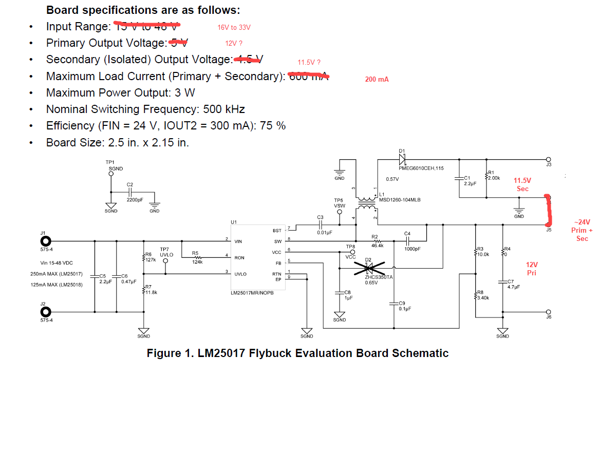
I am looking into using the LM25017 in Fly-Buck mode to generate approximately 24V output from 16V to 33V input. In order to keep costs down, I would like to use off the shelf coupled inductors. It seems Coilcraft has lots of 1:1 coupled inductors, but also offer some 1:2, 1:3 and 1:10.
My thoughts on how to do this are in the marked up LM25017 EVM schematic, below. I am thinking that if I generate 12V on the primary side, and get about 11.5V on the secondary, I could connect the Ground of the secondary to the V+ of the primary to create approximately 24V total. However, I read in the datasheet that maybe it is best to keep Vout_primary < Vin_min/2? If so, would it be better for me to use a 1:3 inductor, and make V_primary = 6V?
Is the concept that I have here make sense to do, or is this idea silly? One potential benefit of this over a SEPIC design is that I could use the lower voltage primary side to power my LDO for other low voltage logic parts, which should reduce some power loss in the LDO.
Before asking this question, I tried to use WEBENCH to simulate, but I wasn't able to figure out how to change the turns ration of the custom transformer that was automatically placed in the design. Any help with getting started simulating this circuit would also be greatly appreciated.