


My customer test LM5176 EMI radiation,over 80db at 40~80MHz,Please provide solution,thanks.
Test report, circuit and layout as follw:
3122.0215-A1A-SCH.pdf7888.0215-A1B-SCH.pdf2843.0215-layout.pdf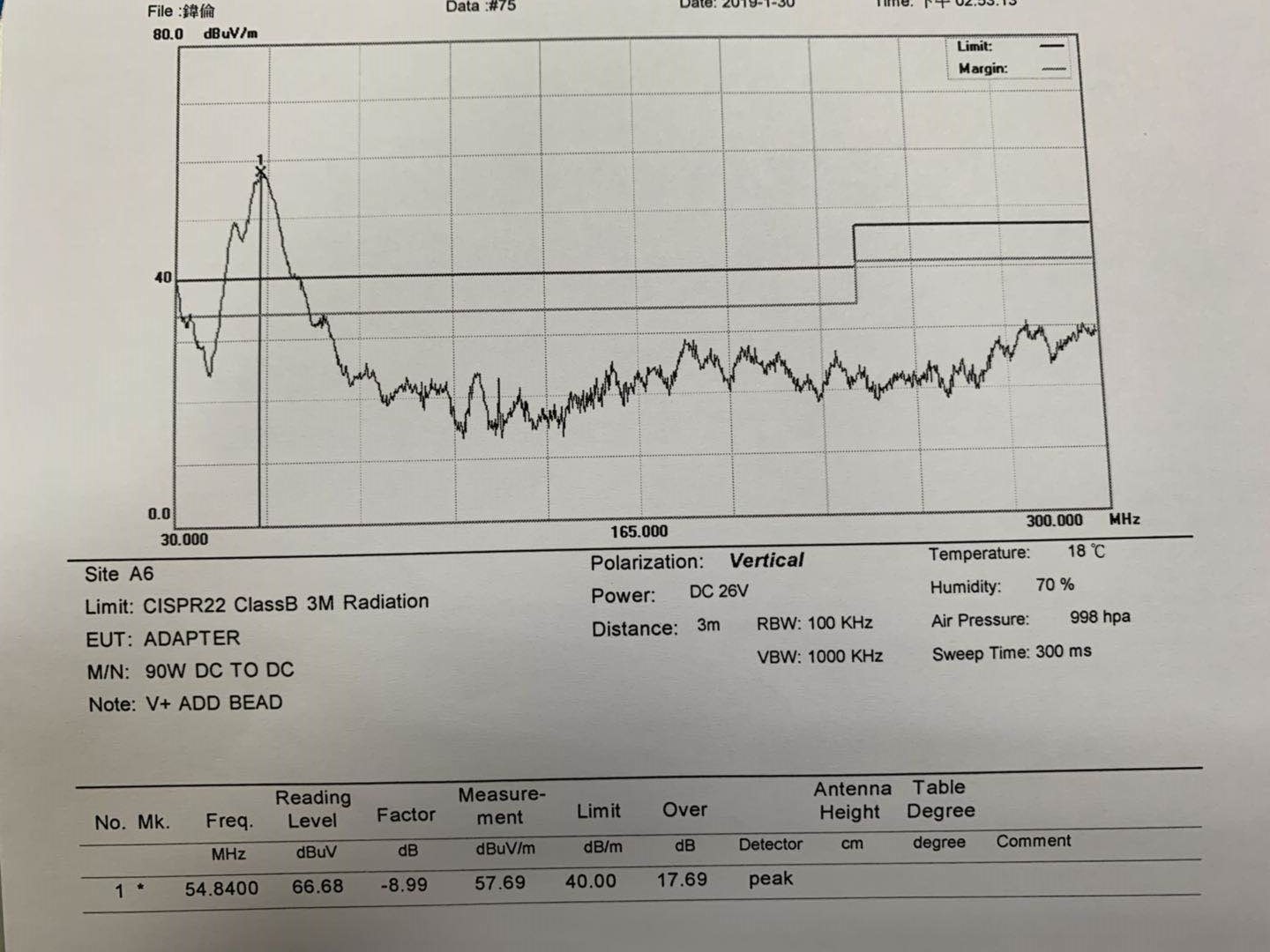
My customer test LM5176 EMI radiation,over 80db at 40~80MHz,Please provide solution,thanks.
Test report, circuit and layout as follw:
3122.0215-A1A-SCH.pdf7888.0215-A1B-SCH.pdf2843.0215-layout.pdf


