This thread has been locked.

If you have a related question, please click the "Ask a related question" button in the top right corner. The newly created question will be automatically linked to this question.

BQ78350-R1: Can't Initialize Discharge

Part Number: BQ78350-R1
Other Parts Discussed in Thread: BQ78350, , BQ76930, EV2400

Hello, 

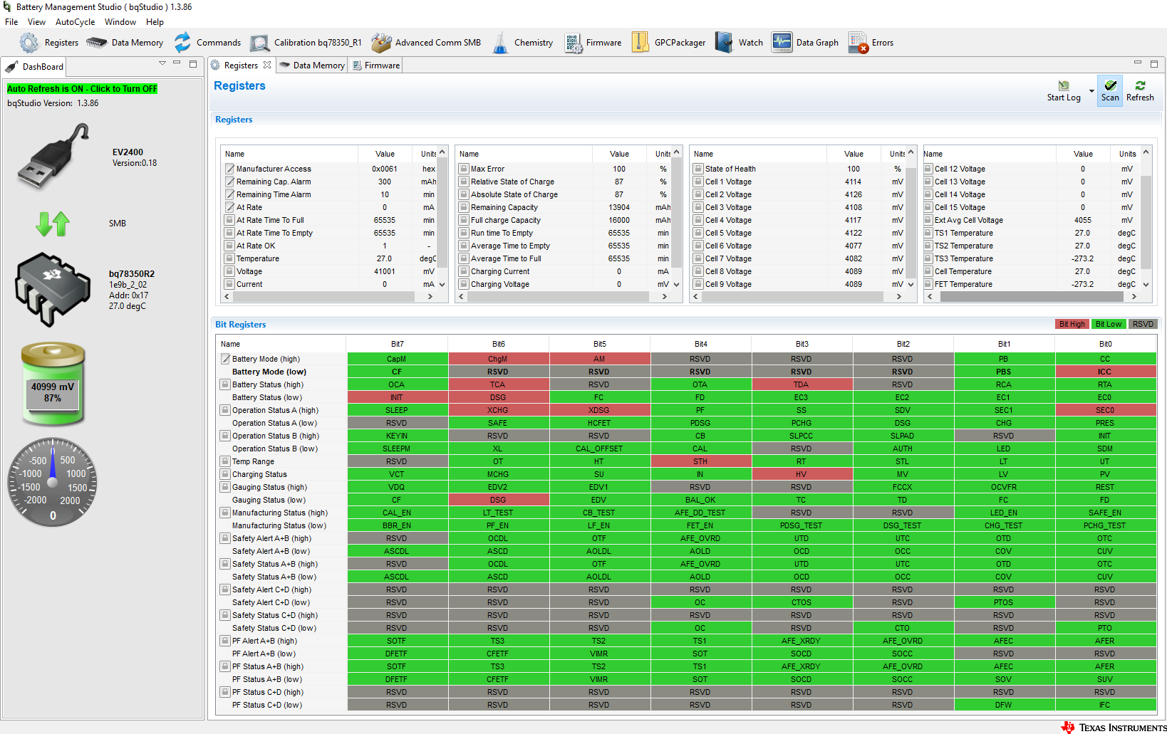
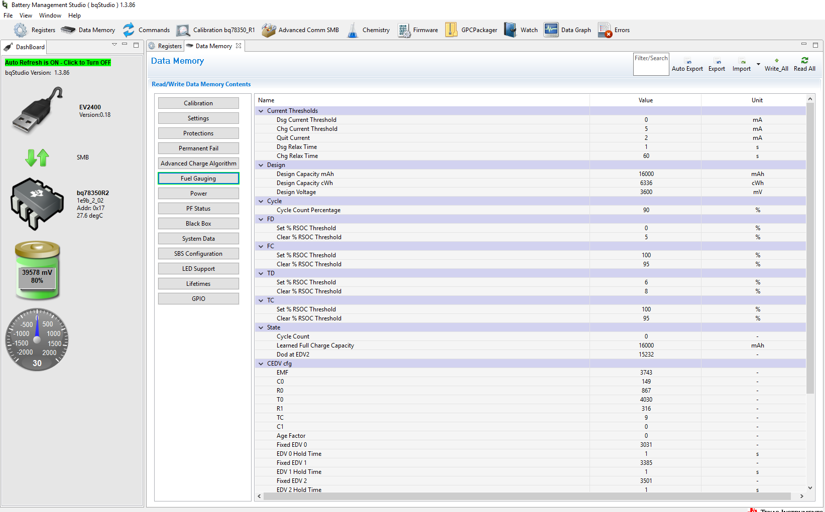
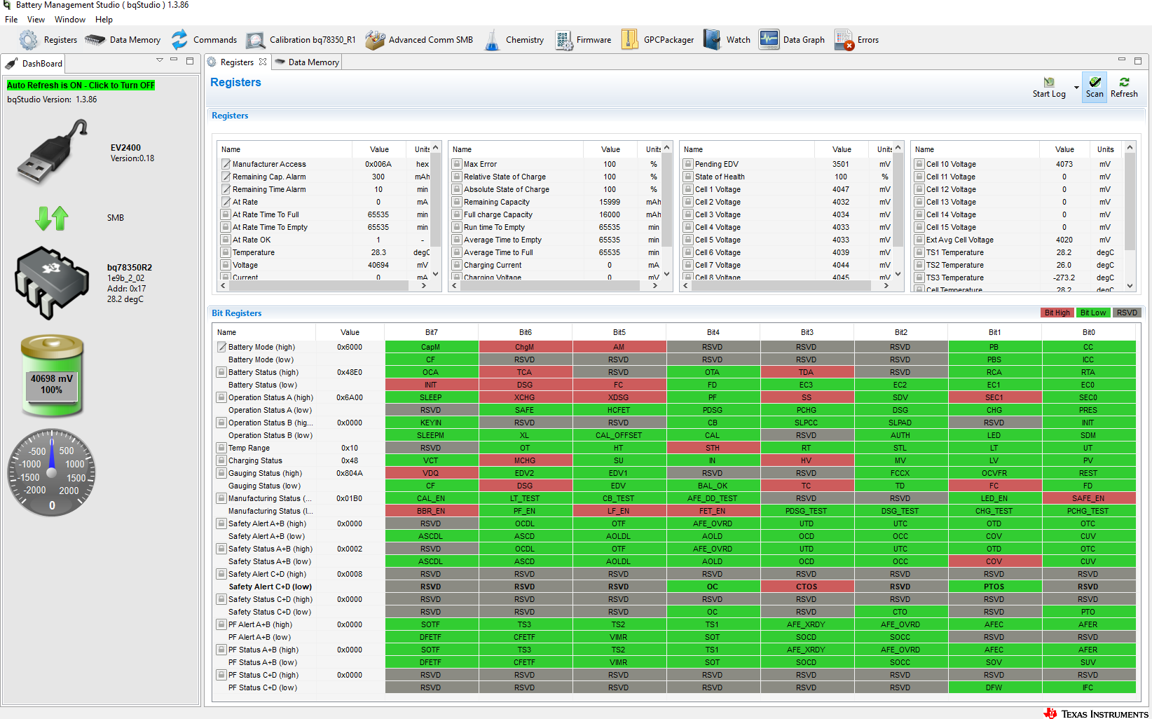
I am at the bitter end of this BQ78350 journey and I have hit a very large obstacle. I need the battery discharge. Unfortunately, the only way I can discharge the battery currently is by initiating a 'Discharge Test'  I have no error flags as you can see in the image. What am I doing wrong? 

  • Hi Drey,
    In the "Manufacturing Status" register, "FET_EN" is not set, so the FETs will not turn on except with the test command as you indicate. In the tools panel, click the "FET_EN" command once, and refresh the register screen. The FET_EN command is a toggle command, so an additional click will turn it off again. You can also set the FET_EN in the Mfg Status Init register in data memory if desired.
    There are other bits the Manufacturing Status register which you may find useful, some can be set from the tools panel. See the bq78350-R1 Technical Reference manual for more information.
  •  Hello WM5295,

    Thank you for the prompt response! I, unfortunately, sent the wrong image. I do have FET_EN selected and I can not get the device to charge or discharge without sending a CHG_TEST or DSG_TEST command. This has led me to question if the BQ76930 is actually recognizing that a LOAD has been applied on the system. I connected a load to the system and measured the CHG pin of the bq76930 as it suggests in SLUA749A (LOAD DETECT page 13). My system uses low-side switching. I did measure the pin was pulled high as the load was applied. How can I test more thoroughly this problem? Also, I attempt to charge the battery with FET_EN selected and I also don't get any response when a charge is applied. Keeping in mind that both the CHG_TEST and DSG_TEST work perfectly what could be the cause of this?  I have attached some of the fuel gauging settings in case they are needed.

  • So, I did some more experimenting and decided to continue charging the batteries using the CHG_TEST register. Once the battery reached fully charged the (VDQ) register went high. This was a new one for me. Must we always fully charge the batteries in production with CHG_TEST before we can get a "Qualified Discharge"?
  •  I have also tested charging now that the discharge function is working and the weirdest thing is occuring. As you can see in the image the (MCHG) maintenance charge register is set while the DSG register is also set. I can see that it is charging however it is not showing that on the gauge?

  •  I have also tested charging now that the discharge function is working and the weirdest thing is occuring. As you can see in the image the (MCHG) maintenance charge register is set while the DSG register is also set. I can see that it is charging however it is not showing that on the gauge?

  • Well, it turns out that my ground lead from my oscilloscope was creating a path around the fets through the same ground of the EV2400. This caused a false dsg and chg scenario. Now that the ground path is eliminated and new bq76930 and bq78350-r1 chips were soldered to the board. I am still having a problem triggering a discharge. I know that the bq76930 is looking for the CHG pin to be pulled to the 16-20v Clamping Voltage as specified in slua749a. I can confirm a solid 17.5V clamp on the Chg pin under load. I also can confirm that CHG_TEST and DSG_TEST passes with flying colors. I will include my .srec in case this can help shed some light on the problem. I am almost 100% sure that this error is due to some  setting I have forgotten. Fingers crossed I can find it soon before my deadline!BMS_FIRMWARE_Original.zip

  • Hi Drey,
    Sounds like you found a setup issue and replaced some bad parts and confirmed the board can flow current.
    In general you want to determine if the board is operating, make configuration settings, check flags and status. Yesterday's pictures may not be relevant now but in the safety registers they show COV which will prevent the charge FET from coming on. In the Operation Status (low) DSG and CHG are low indicating they are off as you indicate, but also PRES is not set. Check the polarity of the pin or connection on the board. PRES must be low to enable the FETs.
    Loading your srec into an EVM it runs fine, the FETs come on. I see the ASCD and AOLD threshold and delay are set at minimum which may be OK for your design, and chemistry is still set at default. There are a lot of settings which should be specific for your board, and you may still have some to optimize, but check the PRES signal. You might also check that the KEY signal is the proper polarity.
  • Well, WM5395 you are a genius!!! It turns out although I have a GND connected to PRES in my schematic, the GND plane I used for the layer wasn't actually reaching to the PRES pin. Rookie mistake! Thank you for all of your help!