Because of the Thanksgiving holiday in the U.S., TI E2E™ design support forum responses may be delayed from November 25 through December 2. Thank you for your patience.

This thread has been locked.

If you have a related question, please click the "Ask a related question" button in the top right corner. The newly created question will be automatically linked to this question.

BQ2002T: Vbatt thresholds and /LED status

Part Number: BQ2002T
Other Parts Discussed in Thread: BQ2002

Having replicated the DV2002L2 design ( http://www.ti.com/lit/ug/sluu007b/sluu007b.pdfand verifying against the potential divider equations in the BQ2002T datasheet I find there are still issues.

It appears the LED logic and potential divider do not conform to what I expected on the datasheet.

1)  /LED status seems to be reversed, high when fast charging monitoring the CC output as a reference.

2)  I want to charge 8 NiMH cells so Rb1= 7Rb2; Rb1 = 100k and  Rb2 = 700k.

To switch over from fast charge the voltage at pin 3 (BATT) the measured voltage was 3.6V, not 2V as per the flow diagram.

With the current configuration the battery voltage required was about 29V, not the expected region of 9.6V

The input voltage is set to 12V regulated by a 7805 for VDD. Increasing the supply voltage doesn't change this behaviour.

BATT inputs and TS are set by a 22k pot for evaluation before disconnecting and feeding battery voltage to BATT for testing.

Thanks in advance.

  • Hello
    Could you send a copy of schematic and layout for review?
    How may boards are you seeing this problem on?
  • Hi Bill,

    Thank you for your quick response.

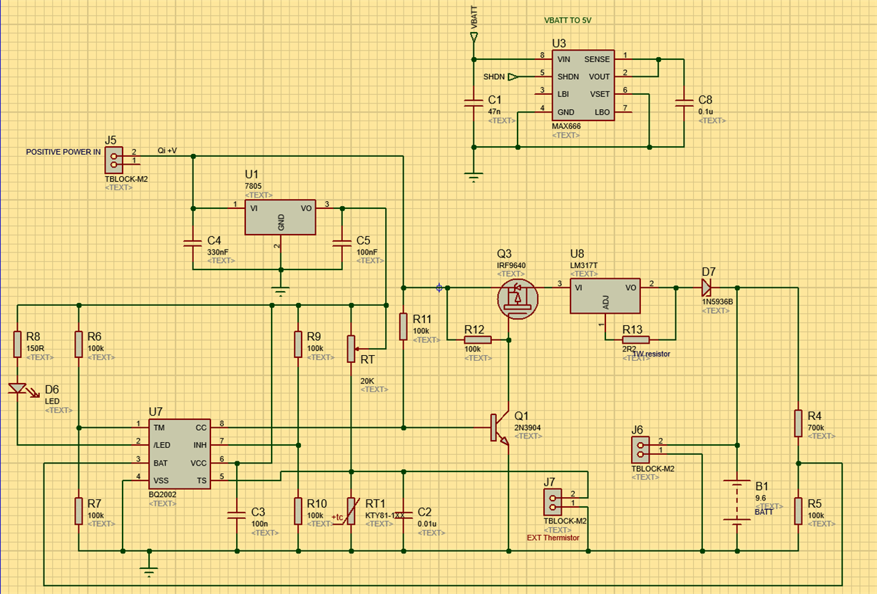
    I've attached the schematic which is representative of the current design, the exception for testing purposes was a trim pot used for battery voltage threshold testing.

    The FET and BJT switching arrangement is to ensure I get the correct response from the device upon BATT reaching a threshold level that will trip it to trickle charge from fast charge.

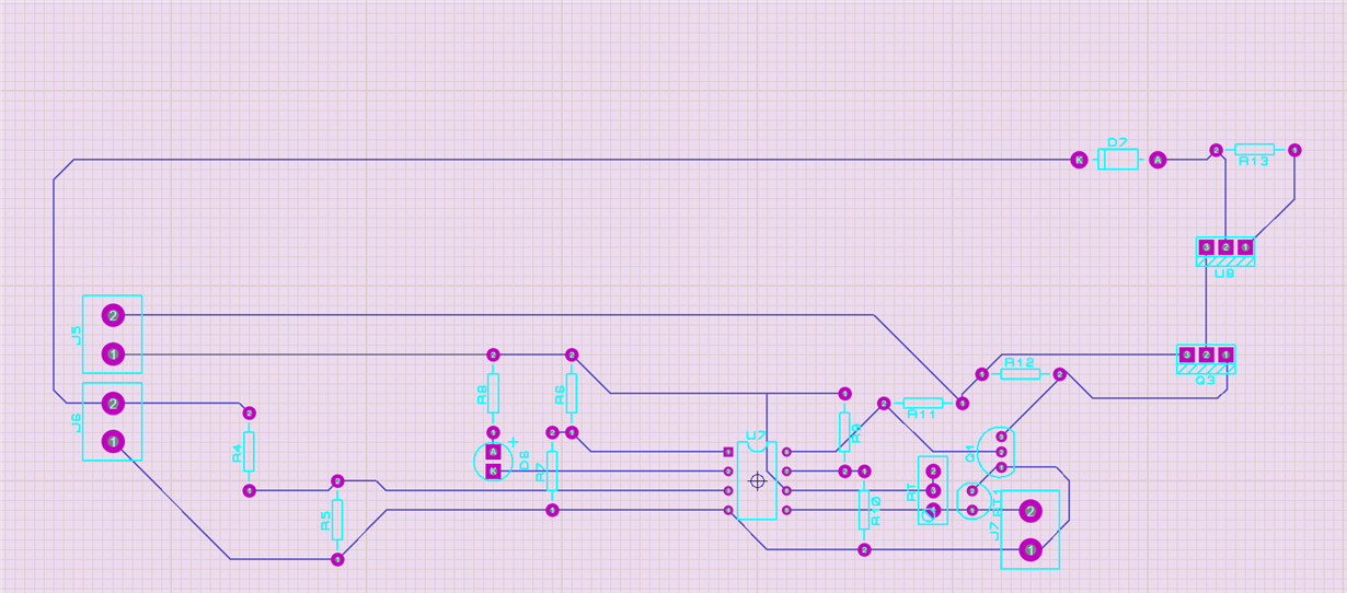
    The layout is very basic and designed on vero board (you might call it strip board) with short track lengths, unlike what has been shown below which is very crude.

    As an additional note, I've noticed that whilst the temperature cut off does indeed switch off the fast charge LED, the CC output still permits fast charge to continue and not set the trickle charge timing periods.

    This is happening both boards ( we are in the evaluation phase with a view to implement these devices).

    Kind regards

    Mark

  • Hi
    Sorry for the delay.

    Double check the U8, Q1 and Q8 current regulator circuit. It is configured differently than the Evaluation board, Q2 and U2.
    U8 should be set up as a current regulator under the control of CC pin 8. With no resistor in the OUT circuit it will act as a 1.2V regulator. (??)

    Update -- With adjust pin at gnd it is a 1.2V reg. But tied to out it may be on all the time.

  • Hi Bill,

    My apologies for my late response also.

    You're quite right about U8, the 2R resistor is between the out pin and Adj as it ought to be.

    Q2/Q1 are arranged like this to overcome the IC not behaving as I expected it to - it's a work around solution with U8 configured correctly.

    Monitoring the BQ2002 pins, /LED and CC exhibit the same incorrect behavior as before when adjusting BATT and TS inputs.

    Any thoughts would be greatly appreciated.

    Thanks

    Mark

  • Hi Mark
    Can you send an updated schematic for review?
    With the additional resistor does the current source work correctly now and have you measured the charge current?
  • Hi Mark
    Any update on this question, is the problem resolved?