From the datasheet of UCC28634:"The peak power mode allows transient peak power delivery up to 200% of nominal rating, with only a 25% peak current increase, maximizing transformer utilization" .we can know the UCC28634 has double power function.
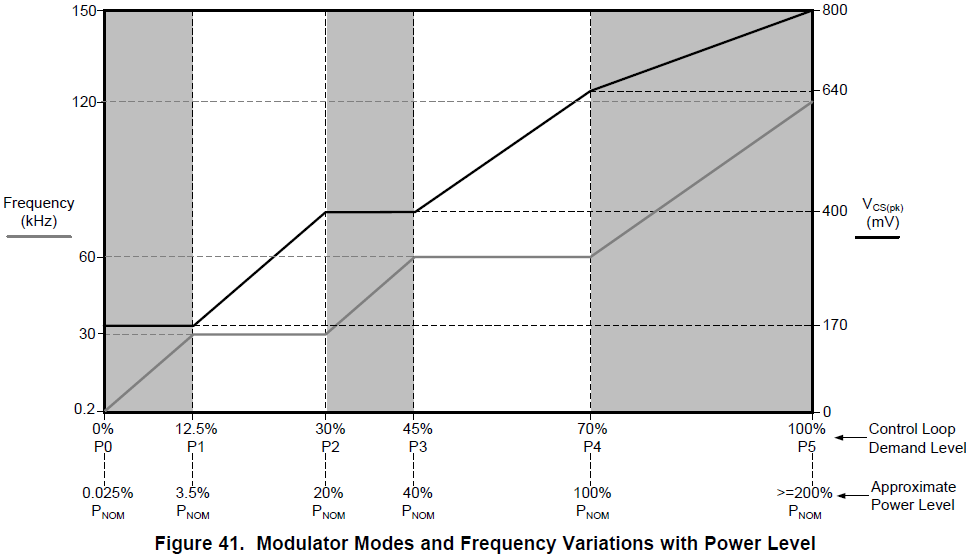
When UCC28634 go into double power,the switch frequency can greater than 60KHz,the Vcs is between 0.64V and 0.8V.
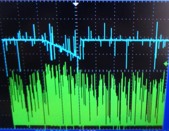
So i make a experiment:the output voltage of load is 27V.I make the current of load change from 1A to 9A.The 9A duration time is 0.2S.The 1A duration time is 1.8S.In the other word,the period is 2S,and the duty is 10%.I can get the following waveforms:
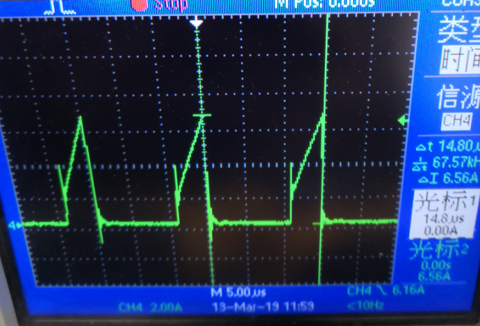
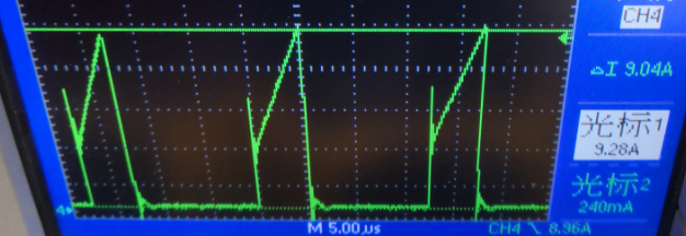
The green waveform is current of main winding.The blue waveform is voltage of output.we can see the voltage of output can be hold on when the current of load change to 9A.And the switch frequency can greater than 60KHz.So i can sure the ucc28634 went into the double power region.
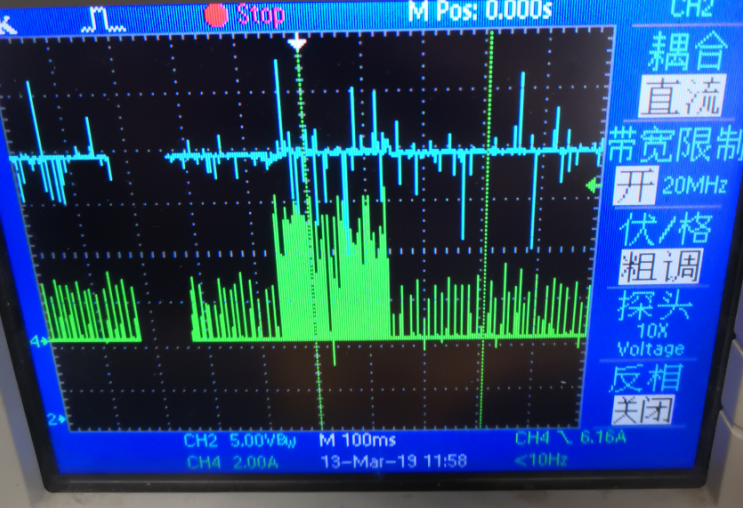
Then I increase the load,I change 9A to 10A.I can get the following waveforms:
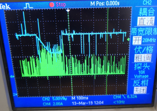
The voltage of ouput is drop down.And the switch frequency don`t increase.So i don`t know why?
In my opinion,the Vcs and the switch frequency will increase when the load increase in the double power region.But the adjustment speed of ucc28634 seems too slow,led the voltage of output drop down.
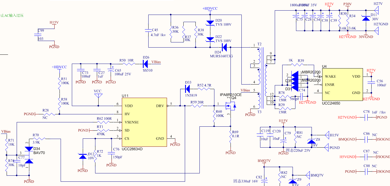
here is my schematic:
Thanks.