This thread has been locked.

If you have a related question, please click the "Ask a related question" button in the top right corner. The newly created question will be automatically linked to this question.

TPS92512: IC pops after a few seconds

Part Number: TPS92512

Hi!

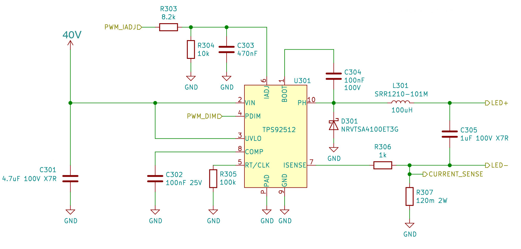
I have been working on getting a 2A LED driver working using the TPS92512 IC for the past couple of weeks.

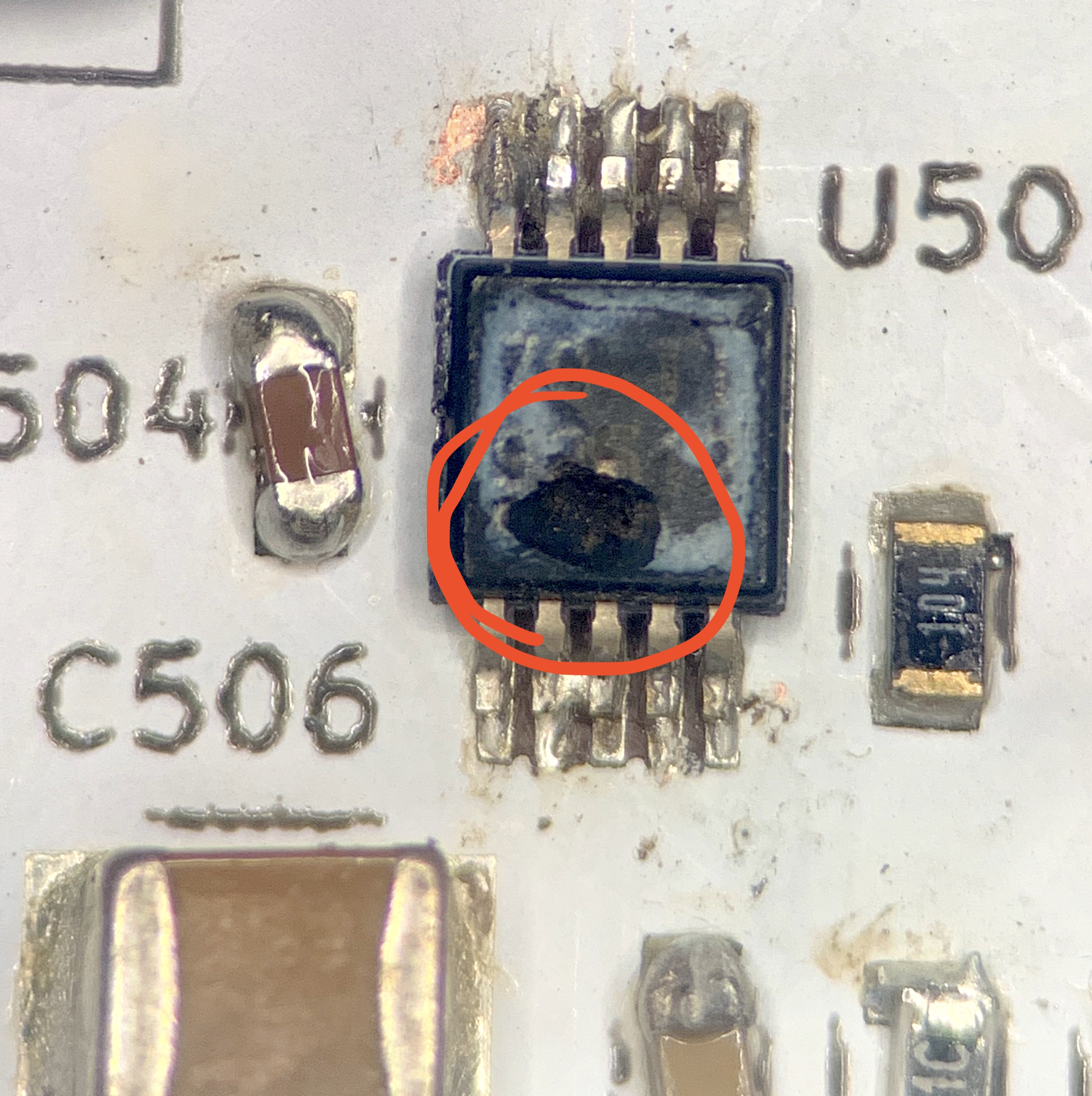
The circuit does function to some extent (it lights up the LEDs for some time and can be PWM dimmed), but after a short amount of time 5-60 seconds the IC pops/explodes and shorting pin 9 and 10. Often it also causes the PWM pin of my STM32 to stop working. This happens also when running at low current ( < 200mA) and PWM duty cycle.

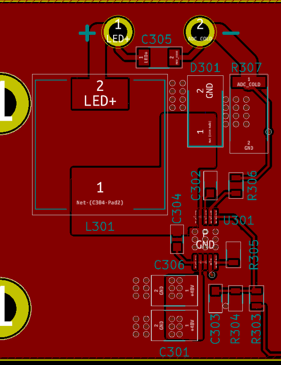
Originally I used a 60V Schottky  diode for D301, which I was advised to upgrade to a 100V 3A Schottky. However this did not resolve my issue with the IC blowing up. I have now made a handful 4 layer PCBs with this which all have suffered from this. I have followed all PCB design guidelines and used high voltage capacitors/diodes. This happens for the HV and non-HV version of the IC.

Details:

  • The power is turned on over about 100ms to avoid any LC spikes from the input capacitor and power supply leads.
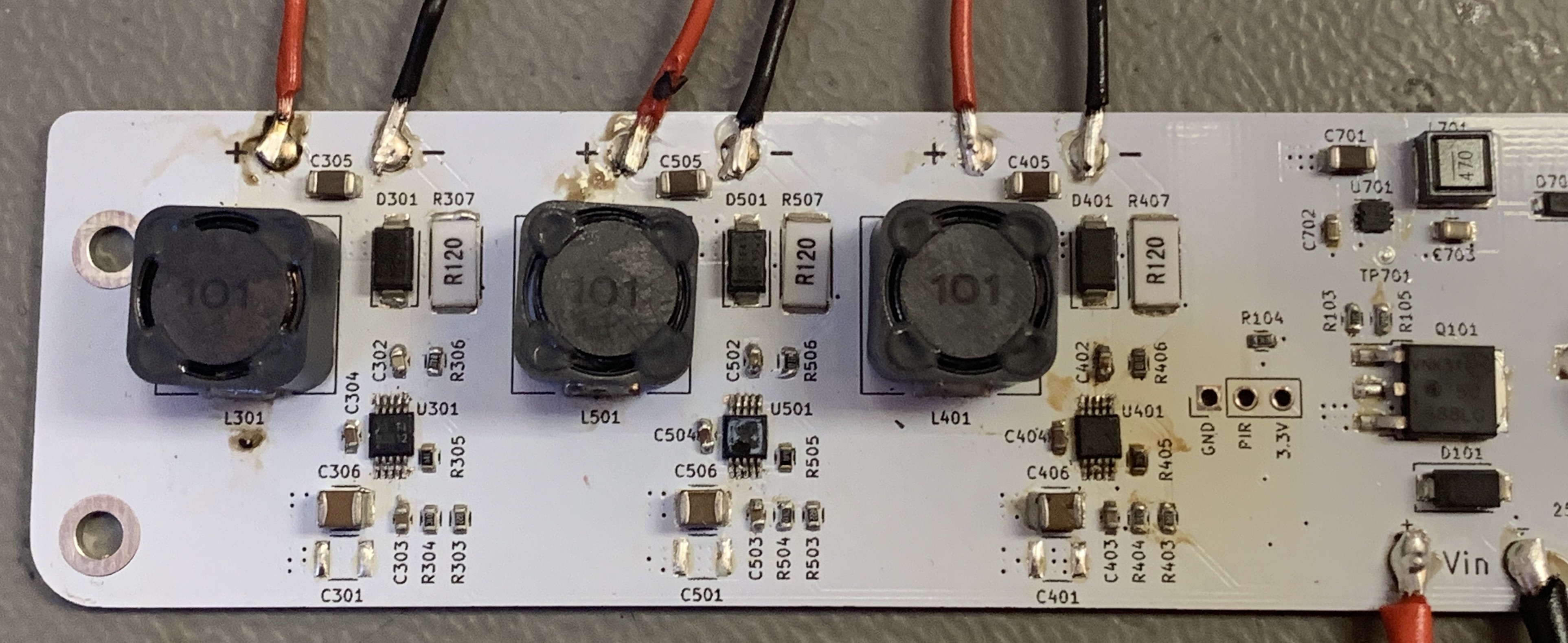
  • LED+ and LED- is connected to an array of 8 strings of 12 white LEDs in series - requiring about 36V to start lighting up.

Am I missing something and can I provide any extra information? (Photos, PCB layout)

  • Below I have attached an image of one of the many blown TPS92512 from the past week and an overview of the three driver circuits:

  • Hello,

    Are you able to look at the output current during operation? Your switching frequency is above 1 MHz with very high duty cycle (if your input is 40V and output is 36V +/-) which means a very short off-time, perhaps even going to 100% duty cycle for some time. I also calculate 2.5A maximum if 3.3V is being used for Viadj. The ripple current is very small with 100 uH and your switching frequency (using 40V input and 36V output). I would try lowering the switching frequency substantially.

    You state that it fails even if at 0.2A output, how are you controlling that?

    It would be good to see what the inductor current looks like during power on and operation until it fails as well as the input voltage and output voltage.

    You may also want to have more maximum current margin on your inductor.  Looking at the inductor current when you have this issue may show that as well.

    Best Regards,

  • Hi Irwin,

    Thank you very much for your constructive response - I will try designing with a lower switching frequency tomorrow morning when I get back to my work desk. And I will try capturing some scope images of the inductor current - until now I have simple not been able to keep it going steady for long enough to capture anything.

    Regarding the inductor, you are suggesting it might saturate or simply overheat?

    I am looking forward to try your suggestions out and appreciate being able to get in touch with a TI engineer :)

    Best regards,
    Jakob Halskov
  • Hello Jakob,

    If you can capture the inductor current, Vin, Vout when it's failing that might be useful. As for the inductor, the datasheet isn't real clear on it's current rating (saturation). This part has a control loop and if Vin is close to Vout it may overshoot as it's powering up (just one possibility out of many), and if the inductor saturates it could cause issues. Waveforms will help diagnose your issue(s).

    Best Regards,
  • Hello Jakob,

    I haven’t heard back from you, I’m assuming you were able to resolve your issue.
    If not, just post a reply below (or create a new thread if the thread has locked due to time-out)

    Best Regards,
  • Hi Irwin,

    After adjusting the components to make the circuit operate at a lower switching frequency with more ripple current in the inductor, the circuit has become more reliable.

    Only when raising the IADJ pin to >1.5V to make it regulate the current to a little above 2 amps the IC popped.

    I am in the middle of making a new revision B of the PCB and will do some oscilloscope measurements when I got it back from the board manufacturer.

    I asume I can let this thread be open and follow up a soon as possible? Otherwise please let me know.

    Best regards,
    Jakob

  • Hello Jakob,

    I will click the TI Thinks Resolved or you can click resolved, for now. If you have issues in the future just reply to the thread and it will re-open.

    Best Regards,