This thread has been locked.

If you have a related question, please click the "Ask a related question" button in the top right corner. The newly created question will be automatically linked to this question.

BQ25710: Questions about the BQ25710

Part Number: BQ25710

Good afternoon,

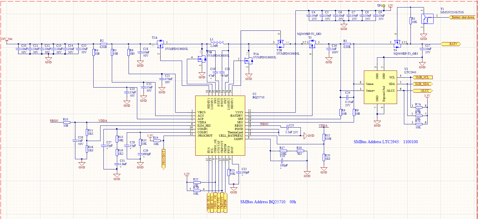
I'm working on a application which uses a BQ25710 charger to power a PCB and a battery. The charger should transform 24V adapter voltage to 12V system voltage.

However during testing it has come clear that I don't get the desired output voltage, I only get 0,1V of output Voltage. When I lower the input voltage to 12V I get 0,2V of output voltage. I found that the gate of mosfet Q1 only gets 0,2V. whichs seems a little less to me. Mosfet Q4 is fully on. So far I didn't connect a battery to the circuit. For the design I used the example shown in the datasheet.

I found that I used different resistor values at the voltage divider connected to Cell_BatPresz. I used a 1kohm and 820ohm resistor to get 55% of the VDDA voltage at pin Cell_batPresz. The datasheet shows resistors with values larger than 100kohm. In my opinion the only difference it should make is that a larger current will occure. 

Some more questions:

- What will happen with VDDA when no battery is connected, will it stay at app. 6V or should it get 0V?

- If the Cell_BatPresz is low, will the charger still provide system voltage to the PCB?

I hope someone can help me solving this issue.

Kind regards

Pim 

  • Hey Pim,

    Can you provide a schematic of your design, specifically the charger?

    What is the voltage on the ILIM_HIZ pin of the charger? This voltage should be above at least 1.2V. If it is above that, what the voltage on REGN? And concurrently, what is the voltage on VDDA?

    CELL_BATPRESZ only stops the charging path, and the voltage at the system should still be regulated.


    Regards,
    Joel H
  • Hello Joel,

    First of all thank you for the quick response!

    Above you see the schematic of how the charger is implemented on the PCB. 

    The voltage on ILim_hiz is 1,4V, the voltage on regn is approx. 6,0V and VDDA is also approx. 6,0V. I removed resistor R12 to get Cell_batpresz low, because no battery is connected to the charger.

    I also noticed that if I start the charger it detects a short, however this has something to do with the system voltage not being higher that 2,7 V at that moment. When I set reg 0x12(6) to 1 and set reg 0x20 (3) to 0 I get 0,1V of output voltage.

    When a battery is not present, will VDDA go low?

    Now it seems that I get 0,7V output voltage when I apply 18V of input voltage. When I apply 24V of input voltage the output voltage will drop to 0.5V. I also measured the pwm signal of Q1 and I noticed that the dutycycle is low, which explains why I get a low voltage.

    Which parameters will have influence on the dutycycle so I get 12V at the output?

    Regards,

    Pim

  • Hey Pim,

    If you don't start the charger (i.e. don't program the charge current and disable the AUTO_WAKEUP_EN bit), is VSYS regulated?


    Regards,
    Joel H
  • Hello Joel,

    I connected cell_battpresz to ground for now by removing resistor R12. Yesterday I noticed that when I reset all registers and give 12 V of input voltage I get 3.6V of output voltage, however if I increase the input voltage the output voltage drops, which will eventually fully disable the converter, because it detects a voltage below 2,7V. I have not been able to get a voltage higher than 3.6V at the output, but it means that the converter at least is able to drive the mosfets.

    What did you think of the schematic of my design? Are there any flaws in the design, which could be problematic?

    Monday I can check the registers you mentioned. 

    Regards,

    Pim

  • Hello Joel,

    I have tested the circuit today with the auto wake up disabled and charge current set to 0. The maximum system voltage I obtain is 3,6V, the input voltage at that moment is approx. 11V. If I increase the input voltage to 13 or 14V the voltage at the output drops below sys_short threshold, which eventually will disable the converter.

    After this test I soldered a new resistor at R12 so cell_battpresz is at a default value to get a default Maxchargevoltage and Minsystemvoltage. When I read this register, I find that the correct values were written to these registers. However(I haven't connected a battery yet so again I write auto wakeup to 0) still my system voltage is regulated not higher than 3,6V. In my opinion the dutycycle of the pwm signal to the gatedriver of Q1 is to low, which limits the output voltage. 

    I also noticed that when I have 3,6V output voltage (Vin is approx. 11V) and I put a load (resistor of 100ohm) at the output, the current of my power supply drops to zero. When I lower the voltage to 8V the current doesn't drop but rises a little bit.

    A last note; could we arrange the we are online at aprrox. the same time? I live in the Netherlands, which means that we don't live in the same time zone. At this moment it's 14:30 in the Netherlands. When we could shorten the time between question and response it would make things easier. If I am right we differ 13 hours from each other. Is it possible to contact each other via this forum at early morning or in the evening?

    Regards,

    Pim 

  • Hey Pim,

    I think I understand what you want and what is going on. 

    When there is no battery attached, the voltage on VSYS will be regulated to VSYSMIN. The system voltage tracks with the battery voltage sensed on VSRN. If VSRN goes higher than VSYSMIN, then the VSYS voltage will follow this as the battery voltage increases.

    You can change the VSYSMIN setting by referring the register table for register address 3Eh, or the MinSystemVoltage Register. By default, the VSYSMIN setting is programmed by the detected value of the CELL_BATPRESZ pin, which in this case has been pulled to ground, setting VSYSMIN to 3.564V as found in the EC table. 

    Regards,

    Joel H